
KL-25 type automatic thyristor excitation device circuit

The circuit in Figure 7-32 is structured to facilitate the effective regulation of excitation in synchronous generators, which are commonly utilized in various power generation applications. The excitation device operates optimally within specified voltage and power limits, ensuring reliability and efficiency in operation.
The SB Kai Lai button functions as a manual trigger for initiating the self-excitation process. When the prime mover accelerates the generator to its rated speed, pressing this button engages the excitation system, allowing the generator to generate the necessary voltage through self-stimulation. This self-excitation process is critical for maintaining the voltage stability of the generator under varying load conditions.
The RPi manual regulator potentiometer is a key component that provides operators with the capability to fine-tune the output voltage of the generator. By adjusting this potentiometer, the operator can either increase or decrease the voltage output, allowing for real-time responses to load changes or system requirements. This feature is particularly important in applications where voltage stability is crucial for system performance.
Furthermore, the RP2 sensitivity adjustment allows for greater control over the excitation system's response to fluctuations. In scenarios where excitation oscillation is detected, reducing the sensitivity can help stabilize the system, preventing potential damage or inefficiencies. This adaptability is essential in maintaining optimal generator performance.
The shutdown procedure, controlled by switch SA, ensures that the excitation system can be safely deactivated when required. By interrupting power to the trigger circuit, the generator can be de-excited without risking damage to the system, thereby enhancing operational safety and longevity.
Overall, this circuit design provides a comprehensive solution for managing the excitation of synchronous generators, integrating manual controls and sensitivity adjustments to optimize performance and ensure stability in various operational contexts. Circuit shown in Figure 7-32. The excitation device is suitable for terminal voltage of 400V, a capacity of less than 75kW synchronous generator motor for automatic adjustment of excitation. Figure, SB Kai Lai button when the generator is pulled to the rated speed of the prime mover, short press the SB, to make electricity to build several self-stimulation voltage; RPi manual regulator potentiometer, RPi reduced ( or increase), the generator voltage drop (or rise Fan). Adjusting RP2, adjustable sensitivity of the device. If the excitation oscillation, can reduce sensitivity try. Shutdown, the switch SA cutoff, trigger circuit loses power, you can achieve generator de-excitation.
Related Circuits
Involvement is a modified version of the classic circuit of automatic level control signal used in tape recorders. The purchase price of the components (using TL072) does not exceed CZK 60 for a channel. For a range of entry...
This device can also be referred to as an economical hearing aid, as it can be constructed using low-cost components. Although its performance does not match that of advanced commercially available hearing aids, it can effectively assist individuals with...
This circuit is designed to detect whether the load of a battery charger or plug-in adapter is properly connected. The load may consist of a set of batteries needing charging or any other device that operates on low DC...
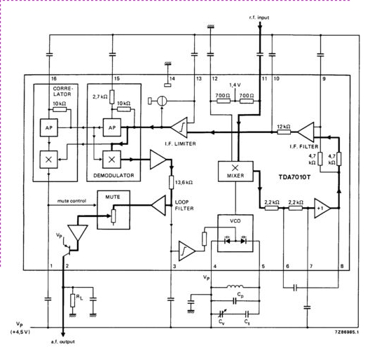
The TDA7010T is a monolithic integrated circuit designed for mono FM portable radios, emphasizing minimal peripheral components to achieve small dimensions and low costs. The IC features a frequency-locked loop (FLL) system. The TDA7010T is engineered to provide high-performance FM...
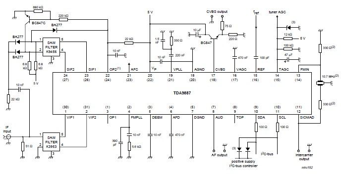
The integrated circuit (IC) is a multistandard vision and sound intermediate frequency (IF) phase-locked loop (PLL) demodulator that operates without the need for alignment. It supports multiple television standards, including PAL, SECAM, and NTSC, and is capable of handling...
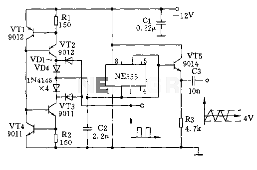
The circuit depicted involves transistors VT1, VT2, and resistor R1, which form a constant current source for charging capacitor C2 in a linear manner. Transistors VT3, VT4, and resistor R2 create a constant current source for discharging capacitor C2,...