
broken charger connection alarm circuit

The circuit operates by monitoring the connection status of the load. It typically includes a voltage divider, a comparator, and an indicator, such as an LED, to signal the connection status. The voltage divider reduces the input voltage to a level suitable for the comparator, which compares the divided voltage against a reference voltage. If the load is properly connected, the voltage at the comparator's input will exceed the reference voltage, resulting in a high output signal. This signal can then be used to illuminate an LED, indicating that the load is connected correctly.
In cases where the load is disconnected or improperly connected, the voltage at the comparator will fall below the reference level, leading to a low output signal. This condition can also be used to turn off the LED, providing a clear visual indication of the issue. The circuit's design ensures that it can operate safely across a variety of battery types and low-voltage devices while maintaining a maximum current of 1A, making it versatile for different applications in battery management systems.
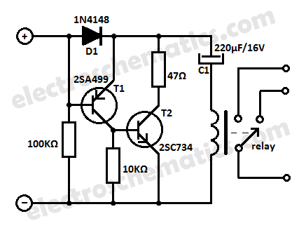
Overall, this circuit serves as a crucial safety feature in battery charging systems, preventing potential damage to the charger or load due to improper connections. Its ability to operate across a wide voltage range enhances its applicability in various electronic devices and systems, ensuring reliable performance and user feedback.This circuit can be useful to detect if the load of any battery charger or plug-in adapter supply is not properly connected. The load can be a set of batteries to be charged or any other type of battery or low dc voltage operated device.
The circuit can safely operate over a 3 to 15V range and 1A max. Current, provided the supply voltage is about one volt higher than the voltage required by the load.. 🔗 External reference
Related Circuits

A multi-stage DC-coupled amplifier circuit utilizes NPN type transistors. Each stage is designed to achieve an appropriate operating point at the base, resulting in a stepwise increase in collector potential, which subsequently reduces the final output voltage range. To...
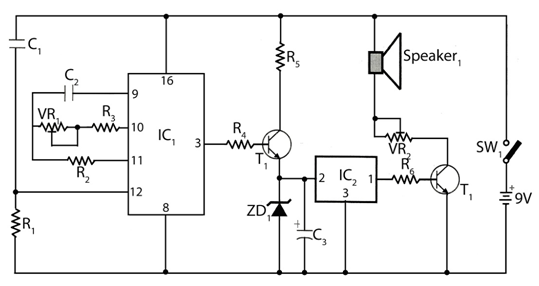
The circuit timer with a musical alarm utilizes a well-known CMOS oscillator/divider integrated circuit (IC1). Although this circuit operates at 9V, its standby current drain is minimal. The time delay of the timer circuit can be adjusted by modifying...
The circuit of the unit is fairly simple, but is a bit irksome to set up. The reason is that obtaining matched FETs is not easy, so I had to make sure that the circuit would work with off-the-shelf...
Protect your equipment with this compact 12V time delay relay circuit. The SMPS-based power supply of modern electronic devices is susceptible to voltage spikes. This 12V time delay relay circuit is designed to safeguard sensitive electronic devices by providing a...
An AM radio receiver circuit utilizing an FM IC chip as the primary component. This AM radio receiver circuit incorporates hand-wound coils to adjust the frequency within the AM bandwidth. The AM radio receiver circuit is designed to capture amplitude-modulated...
This audio noise filter circuit is a bandpass filter designed for the audio frequency range. It effectively filters out unwanted signals that fall below or above the audio frequency spectrum. The audio noise filter circuit operates as a bandpass filter,...