
Incandescent Yeonsu electronic controller 1

The described circuit employs a momentary switch (S) to initiate the operation. Upon activation, the switch allows current to flow through the circuit, but due to the inherent properties of the capacitor (C), the voltage across it cannot change instantaneously. This results in the SCR (Silicon Controlled Rectifier) remaining in a non-conducting state initially, preventing any immediate current flow to the lamp (H). The diode (VD2) allows for a half-wave rectified current to flow, which serves to preheat the lamp. This preheating phase is characterized by a low current that does not significantly illuminate the bulb, thus creating a dim light.
As the capacitor charges through the path defined by diode (VD1) and resistor (R1), the voltage across the capacitor gradually increases. After a delay of approximately 0.6 seconds, the voltage across the capacitor reaches a threshold that is sufficient to trigger the SCR. Once the SCR is activated, it allows current to flow freely to the lamp, resulting in full illumination.
This design effectively incorporates a delay mechanism that prevents sudden surges of current to the lamp, which can be detrimental to its lifespan. By allowing the lamp to warm up gradually, the circuit not only enhances the operational life of the bulb but also improves the user experience by avoiding abrupt lighting changes. The use of the half-wave rectification ensures that the lamp receives a controlled amount of power during the initial preheating phase, further contributing to the longevity of the component. Circuit work process is: When the momentary switch S between, since the voltage across the capacitor can not change suddenly, the Pi C zero voltage across the SCR vs no trigger voltage cut-off stop. In this case the current flowing through the lamp H is through diode VD2 half-wave rectified current, the preheating dark light bulb, the impact of current is very small. If the capacitor C via VDI and Rl charge, after a delay of about 0.6s, C rises to reach the voltage across the controllable silicon vs opening level, vs opened, namely normal lamp H lights up.
Since the bulbs from the cold state to the normal light room with 0.6s buffering delay time, so the lamp life has been extended.
Related Circuits
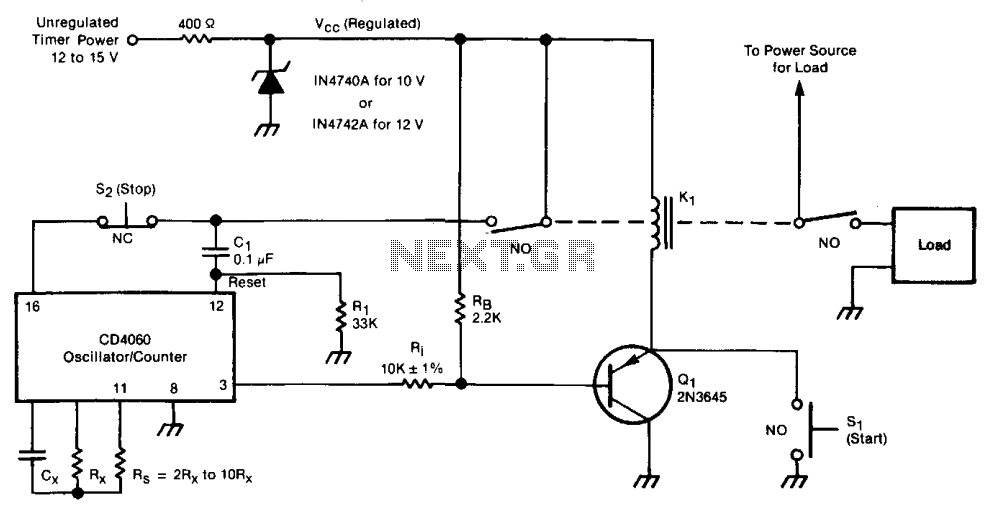
The timer consists of an oscillator and a counter integrated into a single circuit. The timing interval is calculated by multiplying the oscillator period by the number of cycles to be counted. The frequency of the oscillator is influenced...
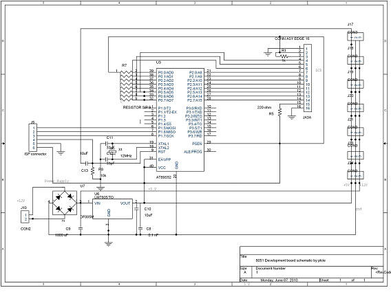
DTMF-based Robo Car design using the 8051 microcontroller project. This project demonstrates a method to control a domestic system using the DTMF tone generated by a telephone instrument when the user presses the keypad buttons of a mobile phone...
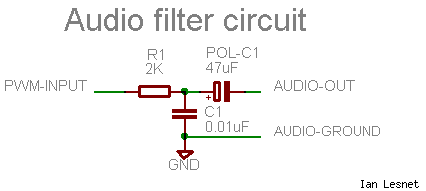
The signal from the MSP430 PWM pin is not suitable for directly driving a speaker or amplifier. To improve the signal quality, it is advisable to process it through a low-pass filter, which smooths out the sharp edges of...
A very simple controller circuit with impressive performance. If a fully automatic computer-controlled rotator is not affordable but enhanced capability is desired from a basic rotator, the ZL1BPU Rotator Controller offers a simple "point and shoot" computer-controlled antenna solution....
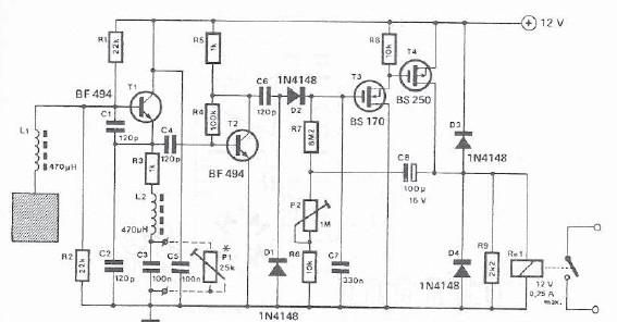
A simple proximity detector can be created using this electronic circuit. This circuit responds to the presence of a conductive object within a specific range. The sensitivity of the circuit can be adjusted with potentiometer P1 to achieve the...
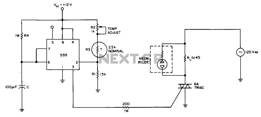
The internal comparator of the 555 timer, combined with a thermistor, creates a low-cost temperature controller. Resistor R2 establishes the temperature trip point. The 555 timer is a versatile integrated circuit widely used in various applications, including timers, oscillators, and...