
Long-term electronic timer
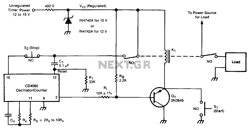
This action grounds one side of relay K1, activating the relay and closing the switches that supply power to the timer and the load. The application of Vcc to the timer is coupled through capacitor C1 to the counter-reset terminal, resetting the counter. The initial reset voltage transient is subsequently drained through resistor R1 to allow for normal operation. During the first half cycle of the counter's operation, the counter output voltage at pin 3 remains low. This condition activates transistor Q1, which latches relay K1 on, allowing the timer to continue functioning even after switch SI is released. The oscillator remains operational while the relay is engaged. Once the number of oscillator cycles reaches the predetermined limit, the counter output voltage at pin 3 transitions high, turning off Q1, which deactivates the relay and returns the system to its original "power-off" state, ready for the next start command. The timing cycle can also be interrupted, and the system can be turned off by opening normally-closed switch S2.
The timer circuit serves various applications in automation and control systems where precise timing is essential. The design integrates an oscillator and a counter, allowing for flexible timing intervals based on component selection. The oscillator's frequency is determined by the values of resistor RS and capacitor CX, which can be adjusted to achieve the desired time constants. The counter's output, accessed through pin 3, provides a digital signal that indicates the completion of the timing cycle.
The relay K1 plays a crucial role in controlling the power supply to the timer and the load. Its activation through the grounding of one side allows for a seamless transition into the timed operation. The reset mechanism, facilitated by capacitor C1, ensures that the counter starts from a known state at the beginning of each timing cycle. The use of transistor Q1 for latching the relay enhances the reliability of the timer, enabling it to maintain operation independently of the momentary switch SI once engaged.
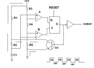
This timer circuit is designed for robustness, allowing for long-duration timing applications and quick interruptions through switch S2. Its versatility makes it suitable for various electronic projects, from simple home automation tasks to complex industrial control systems. Proper selection of the timing components and configuration of the circuit will yield a reliable timer capable of meeting a wide range of timing requirements.The timer includes an oscillator and a counter in an integrated circuit. The timing interval equals the oscillator period multiplied by the number of cycles to be counted. The oscillator frequency depends upon resistor RS and capacitor CX. The number of oscillator cycles to be counted before the counter output changes state is determined by the selection of the counter output terminal, shown here as pin 3. The interval can be set anywhere in the range from fractions of a second to months; it is given by = 0.55 RsCx2n, where is an integer determined by the counter-output selection.
Operation is initiated by the closure of momentary switch SI (or by a command signal having a similar effect). This grounds one side of relay Kl, thereby activating the relay and causing the closure of the switches that supply power to the timer and to the load. The turn-on of Vcc at the timer is coupled through Cl to the counter-reset terminal, thus resetting the counter.
The initial reset voltage transient is then drained away through Rl to permit normal operation. During the first half cycle of the counter operation, the counter output voltage (at pin 3 in this case) is low. This turns on transistor Ql so that relay K1 latches on, enabling the timer to continue running even though switch SI has opened.
The oscillator runs while the relay is on. When the number of oscillator cycles reaches the limit, the counter output voltage at pin 3 goes high. This turns off Ql, thereby turning off the relay and returning the system to the original' 'power-off" state to await the next starting command.
The timing cycle can also be interrupted and the system turned off by opening normally-closed switch S2. 🔗 External reference
Related Circuits
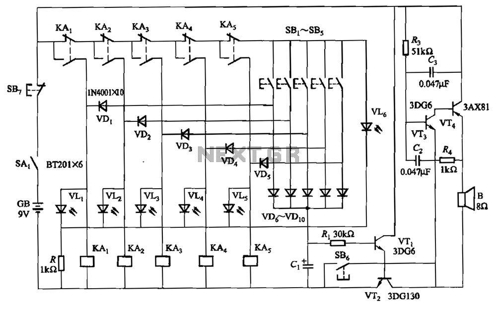
A relay-style circuit designed for a five electronic responder group. This circuit features self-locking capabilities, sound and light displays, time monitoring, and additional functions. The circuit includes a monitoring time button operated by the moderator. When this button is...
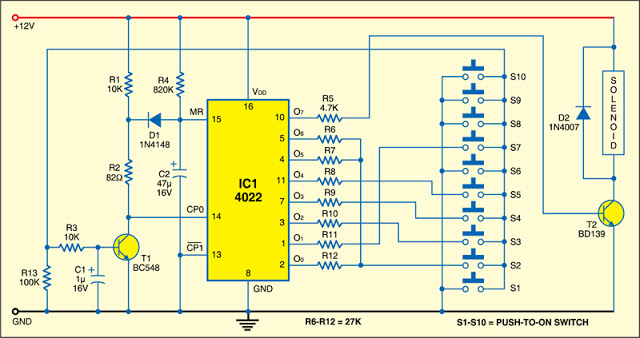
This 7-digit combination lock can be easily hard-wired for any combination that you choose. The circuit utilizes a 4-bit, divide-by-8 Johnson counter (IC1), ten push button switches, and an NPN transistor (T1). Upon power-on, capacitor C2 connected to pin...
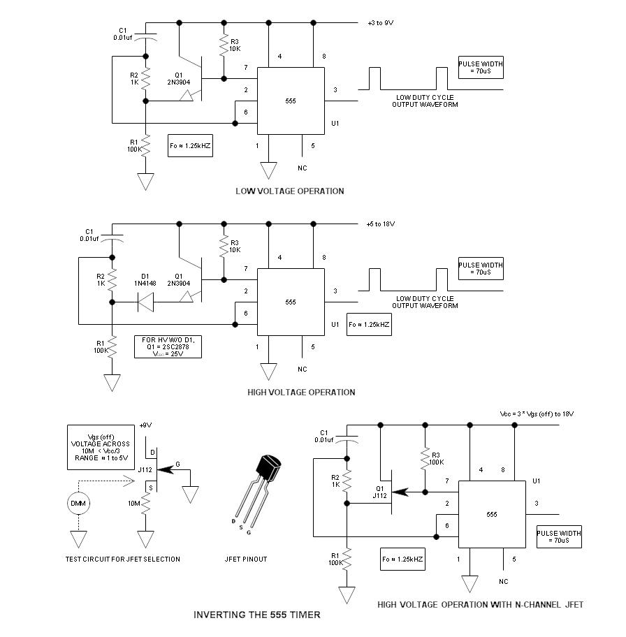
When using the 555 timer, the output polarity often appears to be incorrect, as the 555 typically cannot produce a duty cycle of less than 50%. This inverted 555 circuit is capable of generating duty cycles below 50%. The...
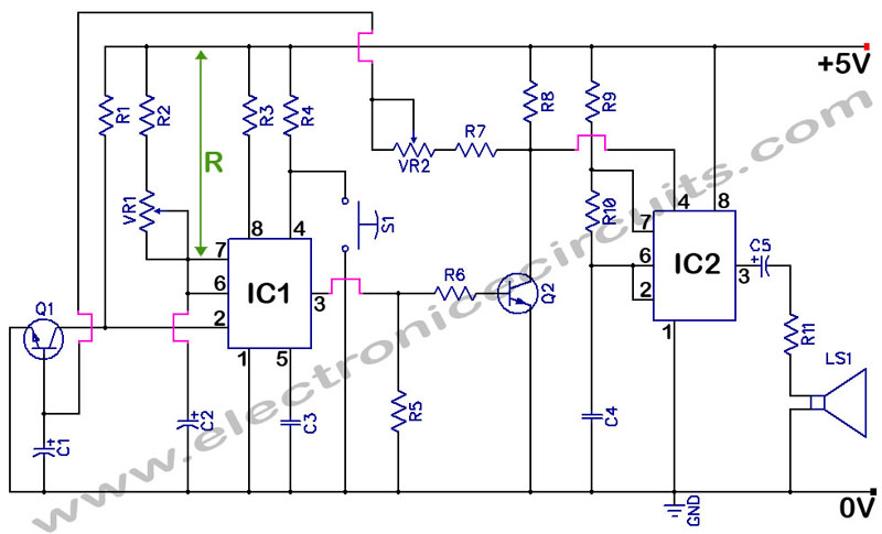
555 Timer with Audio Alarm Circuit. This circuit serves as a straightforward electronic timer equipped with an audio alarm feature. The 555 timer is a versatile integrated circuit widely used in various timer, delay, pulse generation, and oscillator applications. In...
A 555 timer IC is utilized as an astable multivibrator, as illustrated in the accompanying figure (A). The threshold input is connected to the trigger input (Pin 2). The resistor R1, resistor R2, and capacitor C1 form the timing...
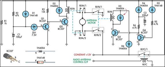
This up/down timer was designed to control a power antenna on a late-model vehicle. Normally, this vehicle uses a body computer to control the antenna. However, the owner intended to install a high-powered audio stereo system. The original stereo...
Warning: include(partials/cookie-banner.php): Failed to open stream: Permission denied in /var/www/html/nextgr/view-circuit.php on line 713
Warning: include(): Failed opening 'partials/cookie-banner.php' for inclusion (include_path='.:/usr/share/php') in /var/www/html/nextgr/view-circuit.php on line 713