
0-12V 2A power supply

This project involves designing a power supply circuit that can operate either from a mains source using a 2155 or 2156 transformer or from a 16V AC plug pack. The choice between these two options is critical for ensuring safety and efficiency. The recommended plug pack is a 16V AC 1 amp model, which is double insulated, thereby enhancing safety during operation.
In terms of performance, while the 2 amp M 2156 transformer can supply a maximum of approximately 1.4 amps DC output, the 1.5 amp AC plug pack provides a similar rating, making it a viable alternative. The cost considerations also favor the plug pack, as it can be more economical than purchasing a transformer and power cord separately.
Heat management is a crucial aspect of this power supply design. A heatsink is necessary to dissipate heat generated by the power components, particularly the transistor. The heatsink must be appropriately sized, with a recommended trial size of approximately 4cm x 10cm. To ensure that the heatsink is adequately sized, a practical approach is to load the power supply to its maximum rating using high wattage resistors or car lamps. During this testing phase, monitoring the temperature at both the transistor and the heatsink is essential to assess thermal performance.
The heatsink should be mounted in direct contact with the transistor and the printed circuit board (PCB) to ensure efficient heat transfer. Proper thermal contact is vital; any inefficiency in this area could lead to overheating and potential damage to the transistor. Therefore, careful attention must be paid to the assembly and mounting of the heatsink to guarantee optimal thermal management in the power supply circuit.This project has two options. It can be a mains operated project, using a 2155 or 2156 transformer or it can be connected to a plug pack. We recommend it be connected to a 16v AC 1 amp plug pack as these are double insulated and provide complete safety for the constructor.
As we have mentioned in the introduction, the 2 amp transformer M 2156 will not provide much more than 1.4 amps DC output so the 1.5 amp AC plug pack has nearly the same rating. By the time you buy a M 2156 transformer and power cord, the total will be the same as the cost of the plug pack so it should be one of your considerations.
The heatsink is one of the most important components in a power supply. It must provide adequate heat dissipation to protect a heat-sensitive device, from being damaged. All power supplies dissipate heat. Some are more efficient than others but whenever voltage and current are present together, heat will need to be dissipated. The way to select the correct-size heatsink is to build the project and fit a heat sink about 4cm x 10cm as a trial experiment.
Next you need some high wattage resistors or car lamps to load the power supply to its maximum rating (this will depend on the transformer you use). Place one finger on the transistor and another on the heatsink, about 2cm from the transistor, and monitor the temperature rise in both positions.
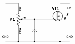
The heatsink in our project fits between the metal side of the transistor and PC board to get direct contact with the transistor. It is most important to get good thermal contact so that any heat generated in the transistor will be carried away by the heatsink.
🔗 External reference
Related Circuits

A CMOS oscillator (U1A) drives U1B through U1F, which in turn drives Q1, generating a 12-Vpp square wave across the primary of T1. This square wave is applied to a rectifier-multiplier circuit consisting of diodes D1 through D10 (each...
This article provides a comprehensive overview of the methodology used for testing power supplies (PSUs) in three main sections. The first section outlines the PSU parameters that are evaluated and specifies the testing conditions. The second section defines commonly...

Unbalanced preamplifier with a single supply. The use of a single power supply necessitates the creation of a voltage that is half of the supply voltage. This half-voltage is generated by resistors R9 and R10, which are configured in...

The foundation of this amplifier is detailed in Project 03, which does not claim to be cutting-edge; the base design is over 20 years old. It is straightforward to assemble, utilizes readily available components, and is stable and dependable....
National Semiconductor has been designing and manufacturing integrated circuits (ICs) for switch-mode power supplies for many years. The application of these devices is typically straightforward, supported by comprehensive documentation. A common example of a switch-mode power supply is based...

The CXA1619BM and CXA1619BS are one-chip FM/AM radio integrated circuits developed by Sony Corporation. These ICs are intended for use in radio-cassette tape recorders and headphone tape recorders, offering a variety of functions. The CXA1619BM and CXA1619BS are designed to...