
pre amp single supply

The unbalanced preamplifier circuit operates with a single power supply, making it suitable for applications where dual power supply systems are impractical. The circuit design relies on a voltage divider formed by resistors R9 and R10 to produce a reference voltage that is half of the supply voltage. This configuration is essential for biasing the input signal, ensuring proper operation of the amplifier.
In this design, the input signal is fed into the non-inverting terminal of an operational amplifier (op-amp) configured for gain. The op-amp amplifies the input signal while the voltage divider provides a stable reference point, allowing the op-amp to operate effectively within its linear region. The output of the amplifier can then be connected to subsequent stages of the audio processing chain or other circuitry.
The choice of resistors R9 and R10 is critical, as their values determine the reference voltage and the input impedance of the circuit. It is essential to select resistors with appropriate tolerances and temperature coefficients to maintain circuit performance under varying conditions. Additionally, bypass capacitors may be included near the power supply pins of the op-amp to filter out high-frequency noise and improve stability.
Overall, this single-supply unbalanced preamplifier design is a compact and efficient solution for amplifying low-level signals in various electronic applications, such as audio systems, sensor interfaces, and communication devices.unbalance pre amp single supply. The use of a single power supply requires the presence of a voltage equal to the voltage divided by two. This half-voltage is created by the resistors R9 and R10 connected in voltage divider bridge. 🔗 External reference
Related Circuits
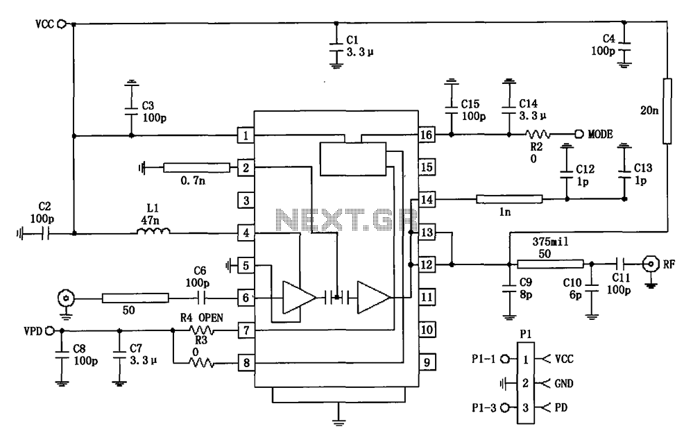
877 ~ 924MHz RF2152 power amplifier circuit diagram. The RF2152 is a high-performance power amplifier designed for applications in the 877 to 924 MHz frequency range. This amplifier is typically used in various RF communication systems, including wireless networks and...
The circuit below is designed to be used with the bi-directional lamp sequencer shown above on this same page. Two additional transistors are used to increase the current from the 74HCT138 decoder to control 12 volt 25 watt lamps....
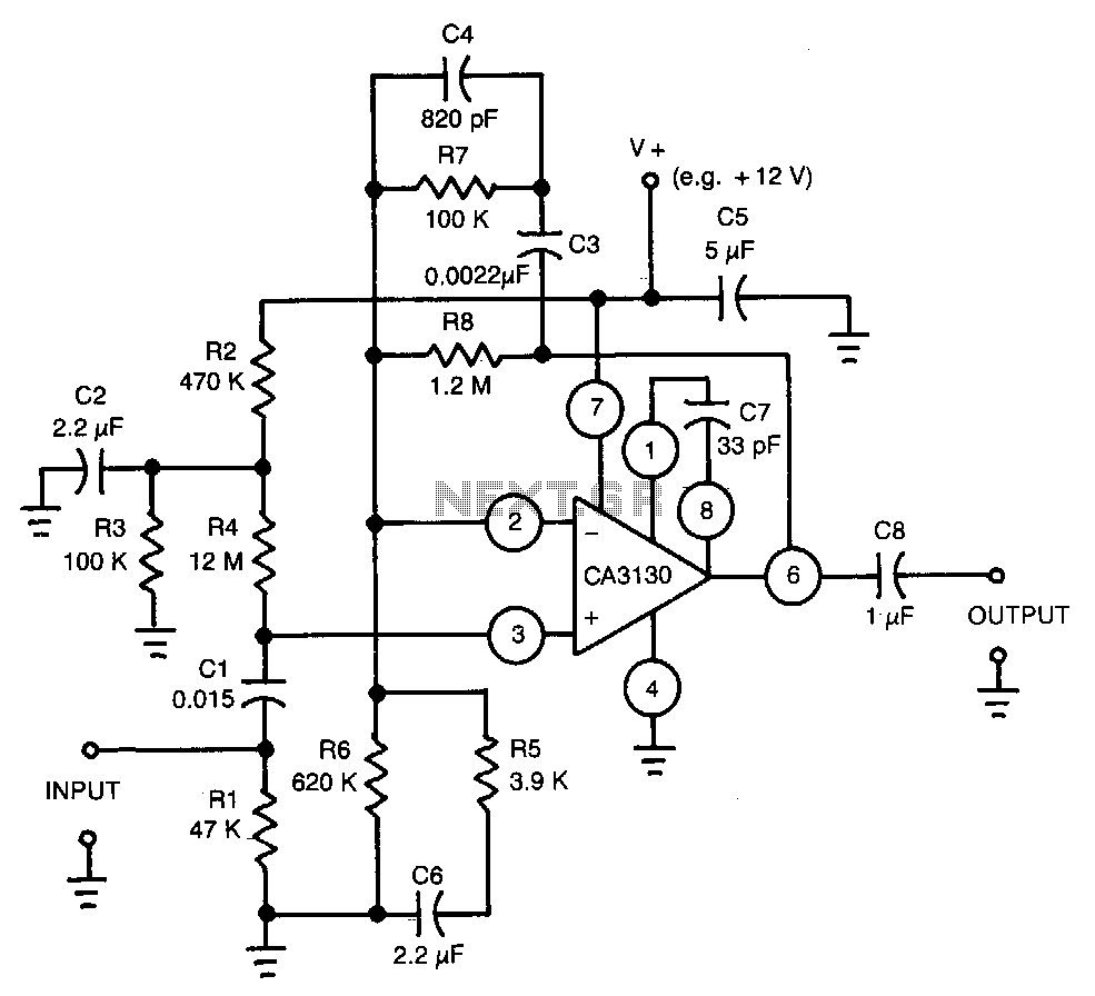
This circuit utilizes a CA3130 BiMOS operational amplifier. The amplifier is equalized to meet RIAA playback frequency response specifications. It serves as a preamplifier following a magnetic tape head. The circuit employs the CA3130 BiMOS op-amp, which combines the benefits...
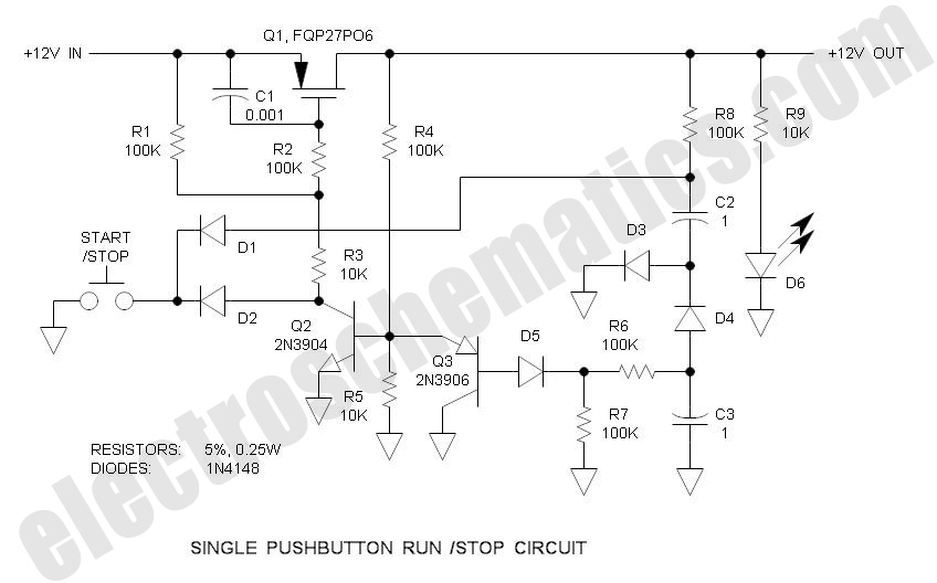
There are solutions to this problem—mechanical (push On/push Off switch), electromagnetic (latching relay), and electronic (CMOS logic), but few (if any) go... In addressing the problem of circuit control, several methods are available, including mechanical, electromagnetic, and electronic solutions. Mechanical...
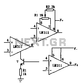
The LM111/211/311 power supply operates within a voltage range of 5V to 15V. It features bias current, offset current, and a differential input voltage range of 30V. The output is compatible with TTL, DTL, and MOS circuits, allowing it...
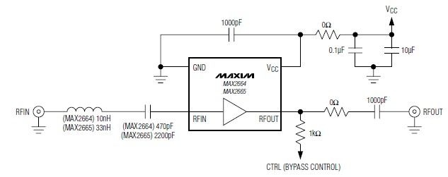
These devices feature a broadband low-noise amplifier (LNA) with an integrated bypass switch. The MAX2664 operates within the UHF frequency range of 470 MHz to 860 MHz, while the MAX2665 functions within the VHF frequency range of 75 MHz...