
0-30 Volt Laboratory Power Supply

The linear power supply circuit is designed to deliver a regulated output voltage ranging from 0 to 30 volts at a maximum load current of 1 amp. The core of the circuit utilizes a discrete transistor as a linear regulator, which is complemented by an operational amplifier (op-amp) that provides feedback for voltage regulation. This feedback mechanism ensures that variations in load do not significantly affect the output voltage, maintaining a stable supply for sensitive electronic applications.
The circuit architecture begins with an AC input, which is first processed by a half-wave rectifier. This rectification stage converts the AC voltage into a pulsating DC voltage. The rectified output is then smoothed using capacitors to reduce ripple voltage, providing a more stable DC input for the subsequent regulation stage.
The discrete transistor, configured as a linear regulator, is responsible for adjusting the output voltage based on the feedback received from the op-amp. The op-amp compares the output voltage with a reference voltage and adjusts the base current of the transistor accordingly. This configuration allows for precise control of the output voltage, making it suitable for applications such as battery charging, where a constant voltage is critical.
In addition to the primary regulation function, the power supply features a constant current mode, which is particularly useful for recharging batteries. In this mode, the circuit can limit the output current to a predetermined value, preventing overcurrent conditions that could damage the battery.
While the original design dates back to 1975, modern advancements in technology suggest alternatives that could simplify the circuit. For instance, integrating a single IC regulator from the MC78XX or MC79XX series immediately after the half-wave rectifier could significantly reduce the component count from approximately 30 to a more manageable number. This integration not only streamlines the design but also enhances reliability and performance. Additionally, replacing the discrete voltage reference diode (D10) with a high-precision zener diode can improve voltage stability and accuracy.
Overall, this linear power supply circuit exemplifies a robust design that balances simplicity and functionality, making it a valuable tool for various electronic applications.The linear power supply, shown in the schematic, provides 0-30 volts, at 1 amp, maximum, using a discrete transistor regulator with op-amp feedback to control the output voltage. The supply was constructed in 1975 and has a constant current mode that is used to recharge batteries.
A more modern circuit might use a single IC regulator, such as the MC78XX, or MC79XX series, immediately after the half wave rectifier, to replace approximately 30 components, or at least a high precision zener diode to replace D10 as the voltage referenc 🔗 External reference
Related Circuits
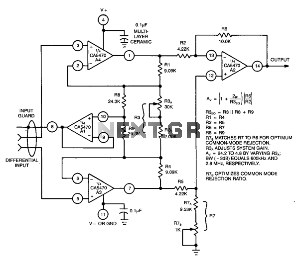
This circuit utilizes a CA5470 quad microprocessor BiMOS-E operational amplifier. Amplifiers A1 and A2 are configured as a cross-coupled differential input and differential output preamplifier stage, while A3 is responsible for input guard-banding. Additionally, amplifier A4 converts the differential...
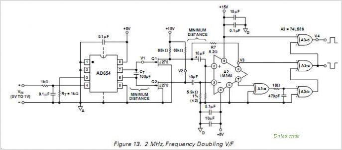
The AD7740 is the smallest and most affordable 12-bit Voltage-to-Frequency Converter (VFC) available. As a synchronous converter, its output frequency is tied to a fixed master clock frequency, which enhances temperature stability compared to asynchronous VFCs. With a 1...
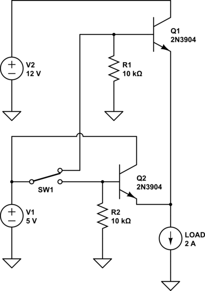
The project involves designing and constructing a breadboard power supply that draws power from an ATX-like switch-mode power supply (SMPS) using a 4-pin Molex connector. The design features a switch to select either a 12V or 5V output. However,...
The two circuits demonstrate the operation of opening a relay contact shortly after the ignition or light switch is turned off. The capacitor becomes charged, and the relay remains closed until the voltage at the diode anode reaches 12...
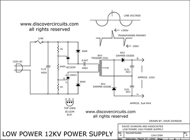
The 12kV High Voltage Generator utilizes a unique adjustment to generate approximately 12,000 volts with a current of about 5 µA. It consists of two SCRs forming two triggering circuit paths. These SCRs discharge a 0.047 µF, 400V capacitor...
This RS-232 to RS-485 protocol converter utilizes two components to form a complete operational system. The circuit adheres to all EIA and ITU specifications for RS-232 to RS-485 RS422 conversion. It features a robust design capable of handling ±15kV...