
Power-Off Time Delay Relay

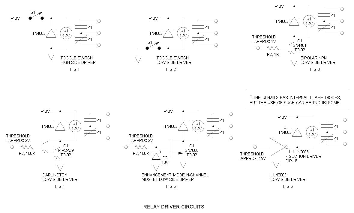
The described circuits utilize a relay mechanism to control the disconnection of a load after a specified delay. When the ignition or light switch is turned off, the capacitor begins to charge through a resistor connected to the power supply. This charging process allows the relay to remain in a closed state, thereby maintaining the connection of the load.
As the capacitor charges, the voltage across it increases. The diode is positioned in such a manner that it allows current to flow into the capacitor while preventing it from discharging back into the circuit. When the voltage at the anode of the diode reaches 12 volts, it triggers the relay to open, disconnecting the load. This delay in opening the relay contact can be adjusted by changing the resistor and capacitor values, allowing for customization based on the specific requirements of the application.
The relay used in this circuit should be rated appropriately for the load it will control, ensuring safe operation. Additionally, the capacitor must have a voltage rating higher than 12 volts to prevent breakdown during operation. The circuit can be further enhanced by incorporating additional components such as a Zener diode for voltage regulation or a transistor for improved switching performance. Overall, this configuration provides a reliable method to control electrical loads with a timed delay, enhancing the functionality of automotive and lighting systems.The two circuits illustrate opening a relay contact a short time after the ignition or ligh switch is turned off. The capacitor is charged and the relay is closed when the voltage at the diode anode rises to 12 volts
🔗 External reference
Related Circuits
Relays have been in use for a considerable duration. Although they are frequently substituted with solid-state switches, relays possess distinct characteristics that render them more robust. Relays are electromechanical devices that utilize an electromagnetic coil to mechanically operate a switch....
A low-pass filter is a stable state-space system that has an input and produces an output. If the input is a quasi-periodic signal, the output will be the same quasi-periodic signal with a phase shift. The key difference is...
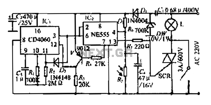
A photosensitive daytime electricity circuit utilizes a very small positive voltage. It features a 555 timer IC with four pins, including a reset pin that operates at low voltage. The circuit includes a bidirectional thyristor (iSCR) that controls lighting,...
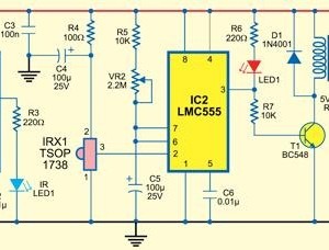
This type of infrared proximity circuit is commonly utilized as an electric switch where physical contact is undesirable for hygiene reasons. For instance, infrared proximity sensors are frequently found in public drinking fountains and washrooms. The straightforward circuit described...
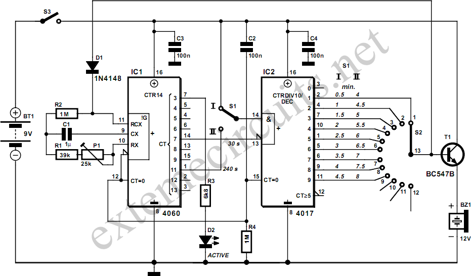
This egg timer, which is both simple and functional, demonstrates that it is not essential to use a microcontroller for everything these days. The circuit consists of only two integrated circuits (ICs) from the standard 4000 logic family, a...
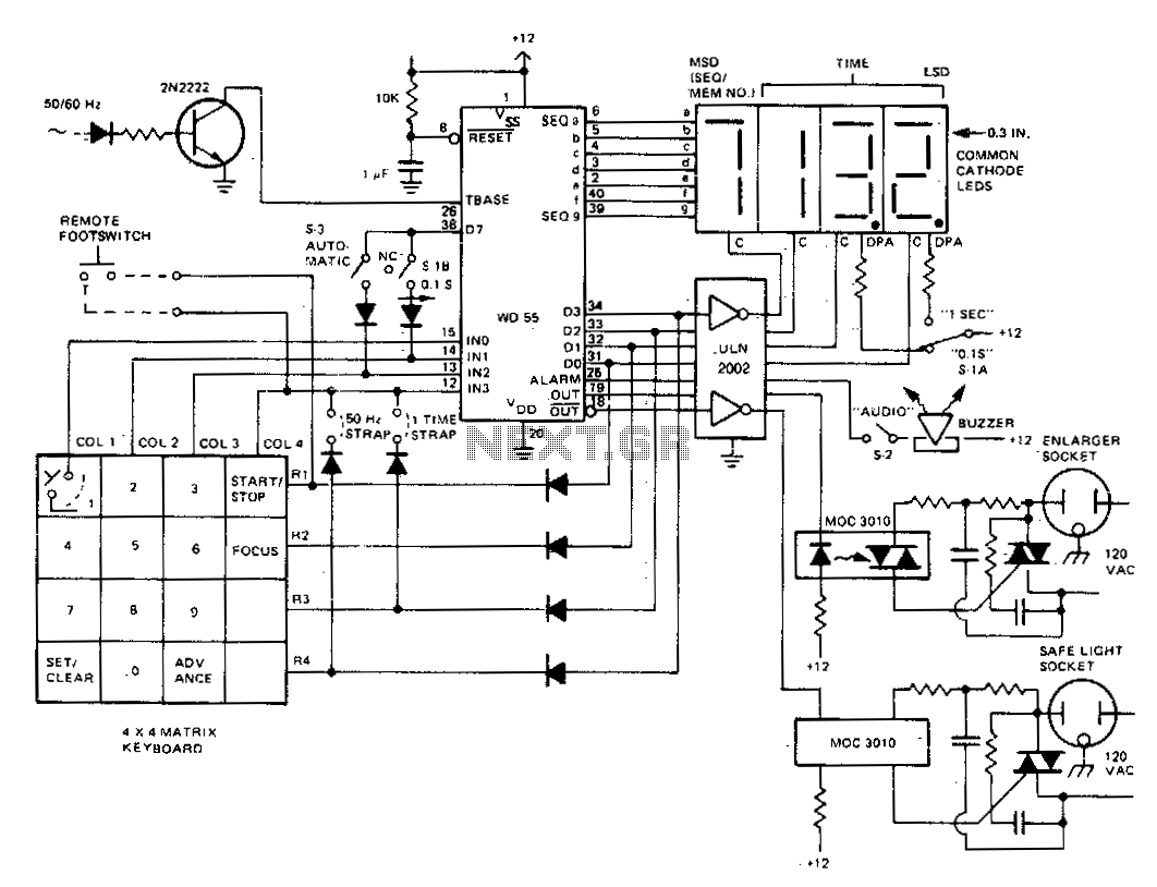
The darkroom timer/controller utilizes a minimal number of external components, including a display, a digit driver, a keyboard, and output switching devices. A 4-digit common-cathode LED display is preferred for use in darkroom settings. The time base is generated...