
0-50V 2A power supply with LM10C

The circuit utilizes the LM10 integrated circuit (IC), which is known for its stable reference voltage, making it suitable for DC power supply applications. The design incorporates two LM10 ICs to achieve adjustable output voltage and current levels. A crucial feature of this circuit is its short circuit protection, implemented through the use of T3, which prevents damage during fault conditions.
Current regulation is managed by potentiometer P2, allowing for a control range of 0 to 2 A. The output voltage stabilization is achieved using resistors R4, R2, and P1, which are connected to the op-amp configuration. Resistor R4 is connected to the negative input of the op-amp, while R2 and P1 are connected to the positive input, creating a feedback loop that ensures stable voltage output.
The op-amp output drives transistor T1, which functions to minimize voltage ripple. T1 adjusts the current flowing through resistor R6, thereby controlling the voltages at T5 and T4. The reference voltage is established at pin 1 of the LM10, and a voltage drop occurs across R1, which is designed to carry a current of 100 µA. This voltage drop is essential for regulating the output voltage by comparing it to the reference voltage from potentiometer P3 and the voltage drop across R11.
For the output voltage to be reduced to 0 V, a 470-ohm resistor should be connected in parallel at the output. The minimum output voltage achievable is 0.4 V, while the maximum output voltage is limited by R1b, ensuring it does not exceed 50 V. To accommodate the power requirements, a transformer rated at 36 V and 3 A is recommended, paired with a 4700 µF capacitor for smoothing the output. Additionally, transistors T6, T5, and T7 require heat sinks to dissipate heat generated during operation, ensuring reliable performance of the circuit.I use the lm10 IC because it has a reference voltage and that?s useful for dc power supply. With two ICs can take different output voltage and amperage. This circuit is protected from short circuit.P2 is for controlling the current at the range of 0-2A. Stabilize the output voltage with R4 on negative pin on op-amp and with R2 & P1 on positive pin. Op-amp output controls T1 that not let ripple of voltage.T1 increase or decrease ampere of R6 and control the voltage of T5 & T4. Pin 1 is the reference voltage and reference voltage is losing some voltage on R1 that has 100uA . This lose voltage regulate output voltage rate of output current is compare between reference voltage of P3 and lose voltage on R11.
T3 is protecting short circuit with R11. For reduce out put voltage to 0v should parallel one resistor 470 ohm in out put. Minimum voltage is 0.4v. The maximum output voltage is fixed with R1b and should not become over of 50v. Therefore your transformer should give 36V, 3A with 4700uF capacitor. T6, T5, T7 need heatsilk. 🔗 External reference
Related Circuits
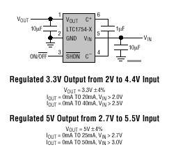
The LTC1754 is a micropower charge pump DC/DC converter that produces a regulated output. The input voltage range is 2V to 4.4V for a 3.3V output and 2.7V to 5.5V for a 5V output. Its extremely low operating current...
Laptops, commonly referred to as notebook computers, have gained significant popularity. Their portable design allows them to be easily transported in a bag, making them suitable for business trips and serving as convenient home entertainment centers due to their...
The primary motivation for utilizing battery power for trains is to eliminate the need for track cleaning and wiring. Track maintenance can pose significant challenges. Incorporating radio control into a battery-powered system enhances command control, an advantageous feature. In...
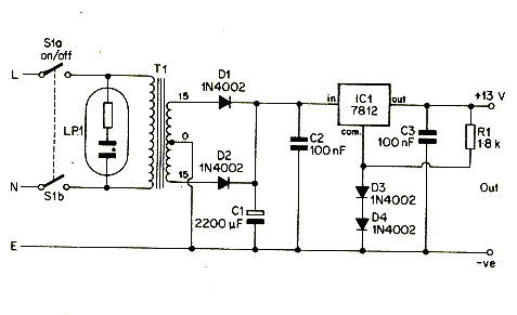
A 12V portable and mobile power supply circuit design that can be constructed at a low cost and requires minimal circuitry. This circuit provides an output current of 1 amp, which is well stabilized and smoothed. The 12V portable power...
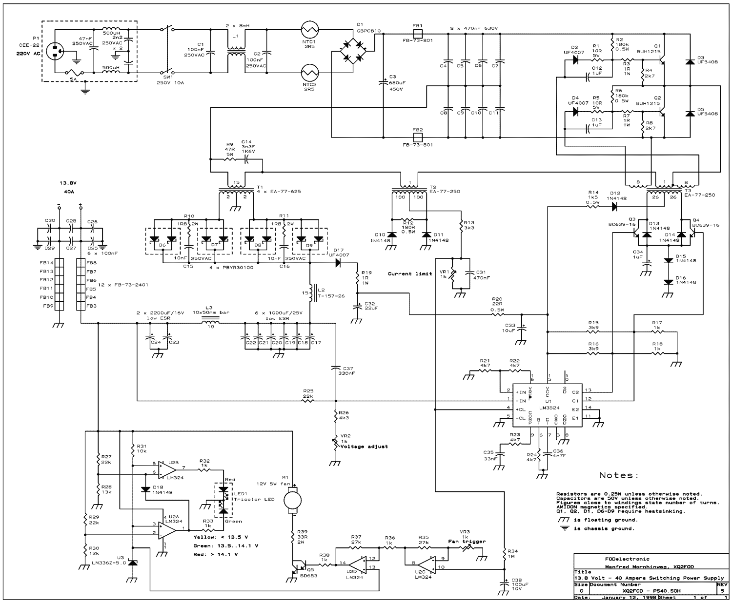
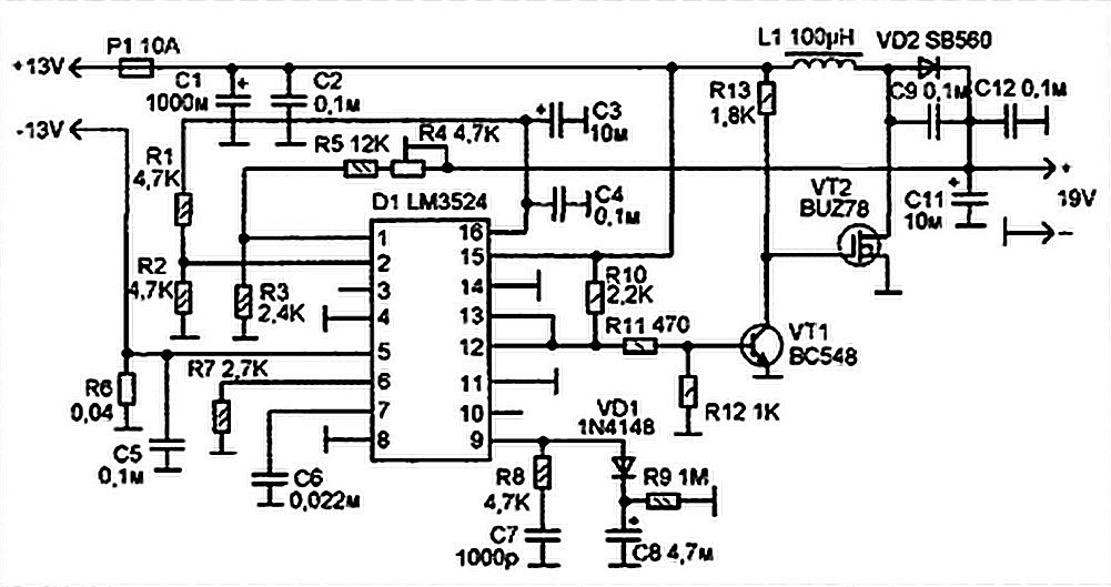
The present trend is to use ever higher frequencies. But by doing so it becomes more difficult to filter out the RF noise inevitably generated by the switching. So I decided to stay at a low switching frequency of...
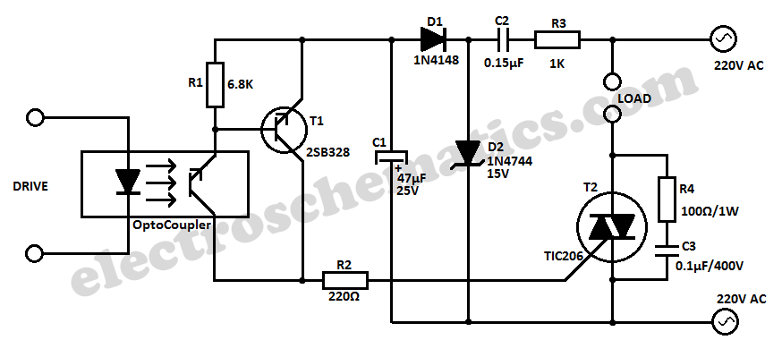
This simple 220V power interface is designed for monitoring electrical equipment and devices using a computer. The interface only detects whether the monitored device is powered on or off. A key feature of this circuit is the galvanic isolation...