
12V Portable and Mobile Power Supply

The 12V portable power supply circuit is designed to deliver a reliable output current of 1 amp, making it suitable for various applications, including powering small electronic devices and circuits. The design utilizes a straightforward approach, ensuring that it can be built with commonly available components, thus minimizing costs.
The core of the circuit typically includes a transformer, a bridge rectifier, and a voltage regulator. The transformer steps down the AC voltage from the mains supply to a lower AC voltage, suitable for rectification. The bridge rectifier converts the AC voltage to DC voltage, which is then filtered using capacitors to smooth out the ripples, providing a more stable output.
After rectification, a voltage regulator, such as the 7812, is employed to maintain a constant output voltage of 12V despite variations in input voltage or load conditions. This regulator is capable of providing the necessary current while ensuring that the output remains stable and within acceptable limits.
Additional filtering capacitors may be included at the output of the voltage regulator to further enhance the stability and smoothness of the output voltage. It is also advisable to incorporate protection features such as fuses or resettable polyfuses to prevent damage from overcurrent conditions.
Overall, this 12V power supply circuit is designed for portability and efficiency, making it an ideal choice for hobbyists and professionals alike who require a reliable and cost-effective power source for their electronic projects.A 12V portable and mobile power supply circuit design which can be built quite inexpensively and needs only a minimum of circuitry. This circuit will give output current of 1 amp, well stabilized and smoothed 🔗 External reference
Related Circuits
This is a portable, high-power incandescent electric lamp flasher. It functions as a dual flasher (alternating blinker) capable of managing two independent 230V AC loads (bulbs L1 and L2). The circuit is entirely transistorized and operates on battery power....
A stabilized voltage inverter that converts 12V to 220V with a power rating of 200W is illustrated in the accompanying diagram. This inverter can utilize an existing dual 12V-200W mains transformer; however, it exhibits low inverter efficiency. The described stabilized...
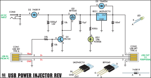
A portable USB hard drive is an effective means to back up data; however, issues may arise if the USB ports do not provide sufficient power to operate the drive. A modified version of the Silicon Chip USB Power...

The circuit illustrated in the figure features an automatic voltage regulator (T) that utilizes a servo motor to ensure a constant output voltage. The transistors used are VT1 and VT2 (3DK9C, with a range of 65 to 85) and...

The circuit illustrated in Figure 3-123 operates as follows: When the stop button SBz is pressed, contact KMi releases, cutting off power to the motor. Simultaneously, KMz is activated, engaging the electromagnetic brake YB to hold the motor in...
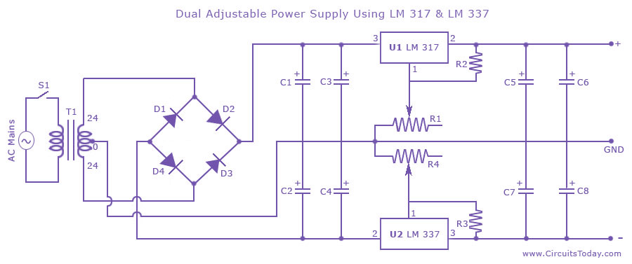
Dual adjustable power supply circuit with a diagram using IC LM317 and LM337. This variable power supply circuit has a range of 1.2 volts to 30 volts. The dual adjustable power supply circuit utilizes the LM317 and LM337 voltage regulators...