
015Watt amplifier schematic

The described amplifier circuit is designed to enhance signal strength in FM radio receivers, which is crucial for maintaining audio clarity and reducing noise. The operational voltage range of 8 to 25 Volts DC allows for versatility in various applications, accommodating different power supply configurations commonly found in consumer electronics.
The circuit typically includes a transistor or operational amplifier configured to amplify weak RF signals received by the antenna. Key components may include resistors to set the gain, capacitors for coupling and decoupling, and possibly inductors for tuning purposes. The output stage is designed to deliver up to 0.15W, making it suitable for driving small speakers or headphones directly.
In terms of performance, the circuit should be optimized for low distortion and a wide frequency response to ensure that the audio output remains faithful to the original broadcast. Proper layout considerations, such as minimizing ground loops and shielding sensitive components, are essential to maintain signal integrity.
The schematic would illustrate the interconnections between these components, providing clear guidance on component values and configurations necessary for achieving the desired performance. This amplifier circuit can be an essential building block for hobbyists and engineers working on FM radio projects, enhancing the overall listening experience.Amplifier circuit is also very suitable when used in fm radio receiver. Supply voltage required 8 - 25 Volt DC with a maximum output power 0. 15W. See Schematic below. 🔗 External reference
Related Circuits
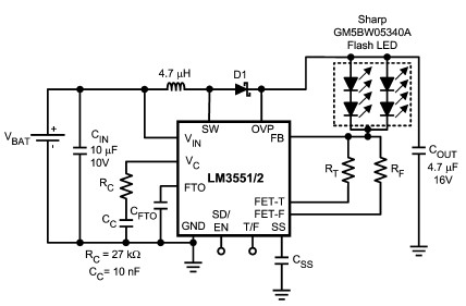
The LM3551 and LM3552 are fixed frequency, current mode step-up DC-DC converters featuring two integrated NFETs. These devices facilitate the design of a straightforward and highly precise LED brightness control system. They are capable of driving loads up to...
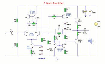
The diagram illustrates a 5W audio amplifier circuit constructed using power transistors BD139 and BD140 for the final amplification stage. This compact amplifier serves as a general-purpose amplifier suitable for applications such as computer audio, radio, MP3 players, and...
By using transformers, both voltage feedback and current feedback can be applied. An article by DJ2LR Ulrich Rohde in Ham Radio, November 1979, provides details about this circuit. For the 2.5 MHz to audio converter, the transformation ratio from...
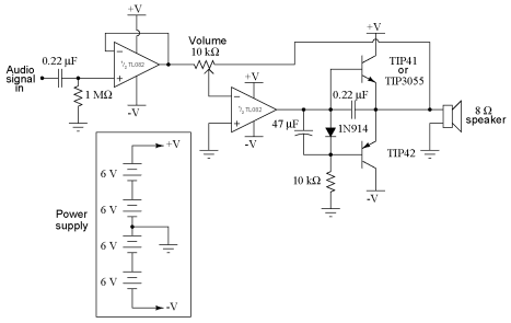
It is advisable to obtain TIP41 and TIP42 transistors, which are closely matched NPN and PNP power transistors with dissipation ratings of 65 watts each. If a TIP41 NPN transistor is unavailable, the TIP3055 (available from Radio Shack) serves...
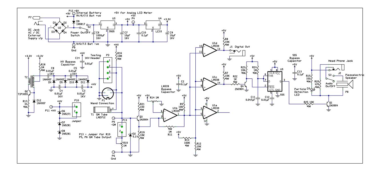
With the recent events at the Fukushima Dai-ichi nuclear power plant, it would be interesting to build a Geiger Counter and connect it to a NerdKit for interfacing with a computer. An article detailing the building process is available,...
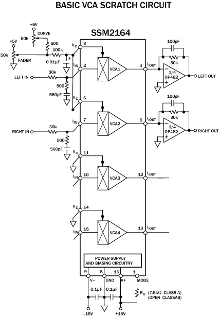
The cut on a fader is fundamentally different from a transform. It is not an instantaneous on/off switch; rather, it features a gradual slope that can range anywhere from a few hundred microseconds to tens of milliseconds. This duration...