
1.8 KHz IC 555Basic Oscillator

The described circuit utilizes the 555 timer IC in an astable mode to create a continuous square wave signal at a frequency of 1.8 kHz. The astable configuration allows the circuit to oscillate between high and low states without any external triggering, making it ideal for generating a consistent tone.
In this setup, the 555 timer is connected with two resistors (R1 and R2) and a capacitor (C1) that determine the frequency of oscillation. The frequency (f) can be calculated using the formula:
\[ f = \frac{1.44}{(R1 + 2R2)C1} \]
To achieve the desired frequency of 1.8 kHz, appropriate values for R1, R2, and C1 must be selected. For example, if R1 is set to 1.5 kΩ and R2 to 10 kΩ, a capacitor value of approximately 10 µF can be used to achieve the target frequency.
The output from the 555 timer is a square wave that can be directly connected to a small speaker or piezo buzzer. The output pin (pin 3) of the 555 timer drives the speaker, producing an audible tone. It is recommended to include a current-limiting resistor in series with the speaker to protect the output of the 555 timer from excessive current draw.
Power supply for the circuit can typically range from 5V to 15V, allowing for flexibility in different applications. The simplicity of this circuit makes it suitable for various alarm systems, timers, or alert signals in electronic projects.
Overall, this basic oscillator circuit provides an effective means of generating a consistent tone for alarm applications, demonstrating the versatility and utility of the 555 timer IC in electronic design.Basic Oscillator (Tone Generator) At 1.8 KHz, IC 555 , Here we have an astable oscillator built around 555, which gives an alarm tone of 1.8 KHz directly driving a speaker. This is basic alarm circuit, whic.. 🔗 External reference
Related Circuits
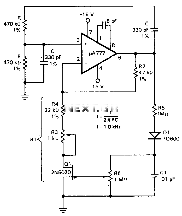
A field effect transistor (FET), designated as Q1, functions within the linear resistive region to facilitate automatic gain control. The attenuation of the RC network is one-third at the oscillation frequency with zero phase shift, necessitating that the amplifier...
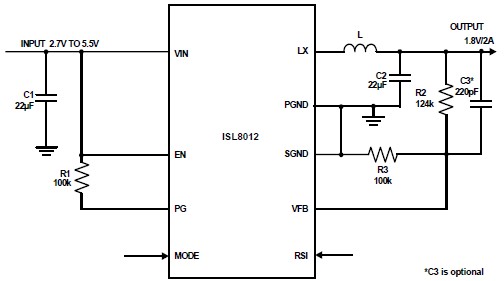
The ISL8012 is a high-efficiency, monolithic, synchronous step-down DC-DC converter that can be designed into a simple electronic project. It supports a maximum continuous output current of up to 2A from an input supply range of 2.7V to 5.5V....
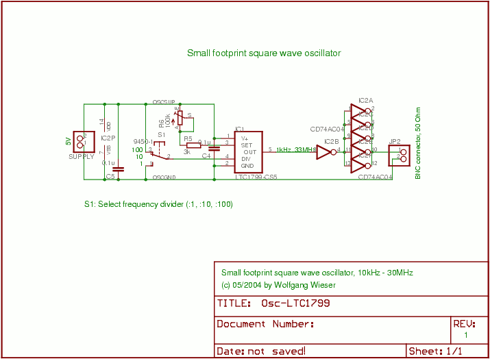
This is a compact square wave oscillator that operates at a 50% duty cycle, with a variable frequency ranging from 10 kHz to 30 MHz. The frequency range can be extended to 1 kHz by substituting a 1 MΩ...
A tutorial on the Wien Bridge Oscillator circuit, which utilizes an RC phase shift oscillator to generate sine waves. The Wien Bridge Oscillator is a well-known electronic circuit used to produce sine waves. It operates based on the principle of...
This circuit operates at 36V with a current of 500mA on the front side, while it features a 36V charging capability on the back side. The brightness is comparable to that of a 240V light bulb, considering it is...
If found myself in need of a 1 KHz signal source for an experiments. My function/sweep generator was needed as a pulse generator for the same experiment, so I went though my junk box, looking for circuits from long...