
Radiant Oscillator

The described circuit appears to be a power supply or lighting system that utilizes a 36V input, drawing a current of 500mA to achieve a certain luminosity. The front section of the circuit likely includes a light-emitting component, such as an LED array or a compact fluorescent lamp, designed to produce brightness equivalent to a traditional 240V incandescent bulb. This suggests an efficient design, as the 20-watt rating indicates that the circuit is optimized for lower power consumption while delivering substantial light output.
The back section of the circuit incorporates a charging mechanism, which is essential for maintaining the operation of the system, particularly if it is intended for portable applications or battery-powered devices. This charging circuit may include components such as a voltage regulator, a rectifier, and possibly a battery management system to ensure safe and efficient charging.
Overall, the design emphasizes efficiency, with the ability to operate at a lower voltage while still achieving high brightness levels, making it suitable for various applications where energy conservation is a priority. The integration of a charging capability further enhances its functionality, allowing for continuous operation without the need for frequent battery replacements.here is a pic running 36v 500ma on the front, 36v charging on the back. Brightness is approaching level of a 240v globe, considering its a 20 watt.. 🔗 External reference
Related Circuits
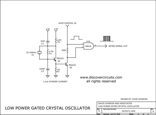
The circuit controls the output of a continuously operating 32KHz crystal oscillator, directing it to the input of a C-MOS buffer when clock pulses are required. This technique addresses the issue of a slow-starting crystal oscillator by maintaining the...
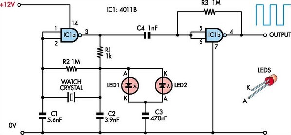
This circuit was designed to enable the use of watch crystals in an existing CMOS oscillator circuit powered by a 12V supply. The challenge arises because these crystals typically operate at a maximum supply voltage of approximately 6V; exceeding...
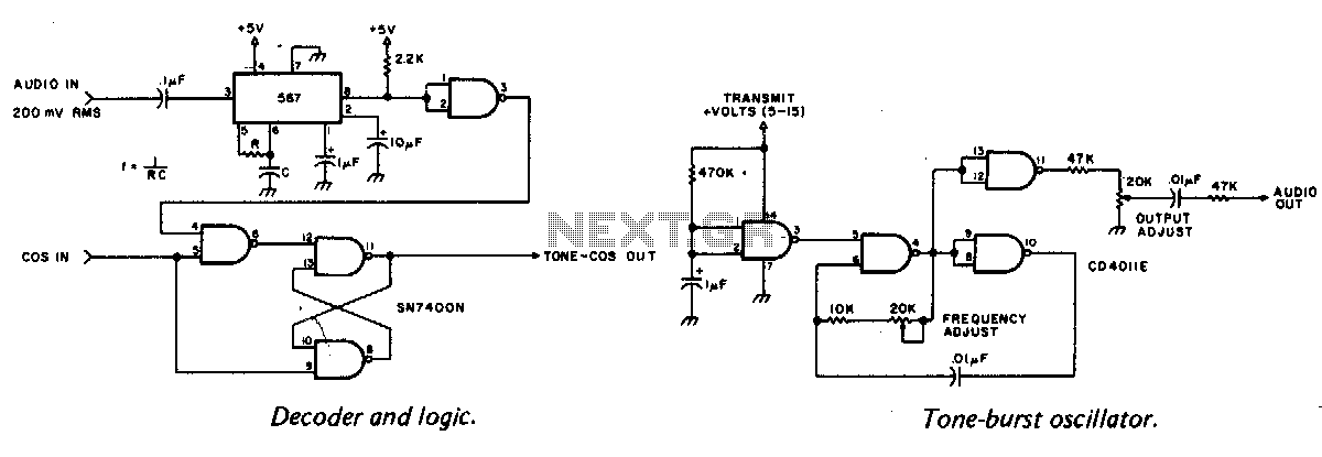
A tone burst sent at the beginning of each transmission is decoded at the receiver by a phase-locked loop (PLL), resulting in an output from pin 3 of a logic gate that activates a carrier-operated switch (COS). In this circuit,...

A useful marker oscillator can be constructed using an NE555 timer to generate pulses at an audio frequency. This design facilitates the detection of the signal even amidst interference. The crystal frequency can range from 1 to 30 MHz. The...

A Wien bridge oscillator generates sine waves with a very low distortion level. It produces zero phase shift at only one frequency (f = 1/2πRC), which becomes the oscillation frequency. Stable oscillation can only occur if the loop gain...
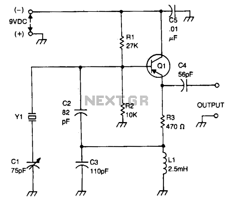
Bias for the PNP bipolar transistor is supplied by a resistor voltage divider network consisting of resistors R1 and R2. The collector of the oscillator transistor is maintained at AC ground through a capacitor C5, which is positioned near...