
1 GHz Frequency Counter

Features
Display range: 0.0 to 999.9 MHz, 0.1 MHz resolution Proper rounding the last digit blinking suppressed Indication of alarms Fast measurement - short measuring cycle High input sensitivity in the VHF / UHF Can be used as a digital scale with respect to the receiver intermediate frequency Technical data
Supply voltage: 8-20 V Supply current: typ. 80 mA, max 120 mA Input Sensitivity: 10 mV max in the range of 1970-1000 MHz Measuring cycle: 0.082 to
Parts List
R1 - 39 to R2 - 1, R3-R6 - 2.2k R7-R14 - 220
C1, C5, C6 - 100 Mini n C2, C3, C4 - 1 n C7 - 100 in C8, C9 - 22 p
IC1 - 7805 IC2 - SAB6456 ( U813BS - different connection terminals, not tested) IC3 - PIC16F84A + programmed base T1 - BC546B T2-T5 - BC556B D1, D2 - BAT41 (BAR19) D3 - HD-M514RD (red) or HD-M512RD (green), four-digit seven-segment LED display controlled by multiplex, you can replace the individual digits X1 - 4.000 MHz crystal Measured from the input signal goes through a pair of Schottky diodes, which should protect the counter against high input voltage. These diodes can be omitted. Here divider IC2, which input signal is divided by 256, to be workable with other districts. After amplification is divided by the signal directly into the processor IC3, the program performs all the remaining functions. The display is controlled by the multiplex, a rapid switching between numbers. Due to the lack of outlets IC3 is a decimal display hard-wired. Screen refresh rate is selected around 49 Hz. Higher frequencies would cause more interference. The connection terminals identified -10.7 will be deducted from the measured frequency value of 10.7 MHz. The counter can thus be used as a scale to the receiver.
Used SAB6456 divider is designed for VHF / UHF applications. The manufacturer guarantees performance in the range of 1970-1000 MHz. It can no longer be used for frequencies from about 3 MHz, but there is much less sensitivity. If not brought to the counter input signal, the divider is sometimes vibrated, reflecting random values on the display screen. This is normal, which allows the manufacturer himself. Overrides are bringing a strong enough signal.
Reviving
Connect the input piece of wire. Insert a pre-programmed into the slot IC3, check the connections and turn on. The display should appear random values in the vicinity of a transmitter will direct its frequency. If you see 0.0, is probably an error in the circuits around the divider, you can also experiment with the value of R1. If you do not see anything or missing segments, the error is around IC3 and displays. If you feel that the displayed frequency is somewhat driving, can be calibrated by changing the counter C8. But it probably will not need the counter resolution is not so large that the deviation of the crystal effect.
Using
The counter can be embedded into a plastic box with transparent front panel input is wired to a suitable RF connector, such as BNC.
When measuring the transmitter input is sufficient to engage the wire with a length of about half a meter. Eg. 3 W output at the correct figure appears as 20 meters from the transmitting antenna. This way you can measure the frequency cordless telephones, radios, bugs and so on. Just close the counter. It is important that the connection counters impair device parameters measured. Divider SAB6456 apparently exists in two versions involved. Both manufactured by Philips, but the other is not bothered to mention in the datasheet. I bought a divider SAB6456 at GM, joined it and did not go according to datasheet. When I did it differently and have struggled to reconcile with the fact that it exploded, so I discovered purely by accident that involved a different outlets. Anyway, I must admit that the last divider really enough, because all my attempts to have survived unscathed. It was also a direct connection to the output of 3 W transmitter, only slightly warm:) The diagram is drawn by the standard of pin under datasheet, circuit board is designed specifically for each engagement. How do you know of pin with dividers that you bought? When you connect to the power of the standard connection and will be taking about 21 mA is connected correctly. If the collection significantly different, a different participating outlets. Divider, which I bought at GM, wearing signs SAB6456, 3540, nJ8135 and the Philips logo.
This counter circuit is designed to measure the frequency of RF signals in the range of 0.0 to 999.9 MHz with a resolution of 0.1 MHz. The device uses a microcontroller (PIC16F84A) to process the incoming signals and display the frequency on a four-digit seven-segment LED display. The circuit includes critical components such as a power supply regulator (7805) to ensure stable operation, and a frequency divider (SAB6456) that reduces the input frequency for easier processing.
The input signal is fed through a coaxial cable, ideally RG58, which is connected to the counter's input port. A loop of wire is soldered to the end of the cable to couple with the oscillator coil, allowing for effective frequency measurement. The circuit also incorporates Schottky diodes to protect against high voltage signals, although these can be omitted if not necessary.
The design emphasizes simplicity and cost-effectiveness, making it accessible for hobbyists and engineers alike. The circuit can be calibrated by adjusting capacitor C8 if needed, although the inherent resolution of the counter typically negates the necessity for frequent calibration.
For practical use, the counter can be housed in a plastic enclosure with a transparent front panel for visibility. An RF connector, such as BNC, can be utilized for input, ensuring compatibility with various RF devices. The circuit is capable of measuring frequencies from cordless telephones to other wireless devices, providing a versatile tool for frequency analysis.This very simple counter can be used to measure the frequency of various wireless devices. Applies in reviving the transmitter and its operation as a control monitor frequency. It can be used as a scale to the receiver. Due to the simplicity of the counter should not miss any of the equipment bastlí?e that similar facilities are still owned. Buying the parts is not a significant financial burden and required the program to the PIC is available for download.
To measure the frequency of the oscillator (either the transmitter or receiver), use coaxial cable (RG58 is suitable) connected to the input port counters. At the end of the cable loop from the solder wire and place it on the oscillator coil. In some cases, the cable can be connected through a resistance of about 1 to the output amplifier stage for the oscillator.
Features Display range: 0.0 to 999.9 MHz, 0.1 MHz resolution Proper rounding the last digit blinking suppressed Indication of alarms Fast measurement - short measuring cycle High input sensitivity in the VHF / UHF Can be used as a digital scale with respect to the receiver intermediate frequency Technical data Supply voltage: 8-20 V Supply current: typ. 80 mA, max 120 mA Input Sensitivity: 10 mV max in the range of 1970-1000 MHz Measuring cycle: 0.082 to Parts List R1 - 39 to R2 - 1, R3-R6 - 2.2k R7-R14 - 220 C1, C5, C6 - 100 Mini n C2, C3, C4 - 1 n C7 - 100 in C8, C9 - 22 p IC1 - 7805 IC2 - SAB6456 ( U813BS - different connection terminals, not tested) IC3 - PIC16F84A + programmed base T1 - BC546B T2-T5 - BC556B D1, D2 - BAT41 (BAR19) D3 - HD-M514RD (red) or HD-M512RD (green), four-digit seven-segment LED display controlled by multiplex, you can replace the individual digits X1 - 4.000 MHz crystal Measured from the input signal goes through a pair of Schottky diodes, which should protect the counter against high input voltage.
These diodes can be omitted. Here divider IC2, which input signal is divided by 256, to be workable with other districts. After amplification is divided by the signal directly into the processor IC3, the program performs all the remaining functions. The display is controlled by the multiplex, a rapid switching between numbers. Due to the lack of outlets IC3 is a decimal display hard-wired. Screen refresh rate is selected around 49 Hz. Higher frequencies would cause more interference. The connection terminals identified -10.7 will be deducted from the measured frequency value of 10.7 MHz.
The counter can thus be used as a scale to the receiver. Used SAB6456 divider is designed for VHF / UHF applications. The manufacturer guarantees performance in the range of 1970-1000 MHz. It can no longer be used for frequencies from about 3 MHz, but there is much less sensitivity. If not brought to the counter input signal, the divider is sometimes vibrated, reflecting random values ??on the display screen. This is normal, which allows the manufacturer himself. Overrides are bringing a strong enough signal. Reviving Connect the input piece of wire. Insert a pre-programmed into the slot IC3, check the connections and turn on. The display should appear random values ??in the vicinity of a transmitter will direct its frequency.
If you see 0.0, is probably an error in the circuits around the divider, you can also experiment with the value of R1. If you do not see anything or missing segments, the error is around IC3 and displays. If you feel that the displayed frequency is somewhat driving, can be calibrated by changing the counter C8.
But it probably will not need the counter resolution is not so large that the deviation of the crystal effect. Using The counter can be embedded into a plastic box with transparent front panel input is wired to a suitable RF connector, such as BNC.
When measuring the transmitter input is sufficient to engage the wire with a length of about half a meter. Eg. 3 W output at the correct figure appears as 20 meters from the transmitting antenna. This way you can measure the frequency cordless telephones, radios, bugs and so on. Just close the counter. It is important that the connection counters impair device parameters measured. Divider SAB6456 apparently exists in two versions involved. Both manufactured by Philips, but the other is not bothered to mention in the datasheet. I bought a divider SAB6456 at GM, joined it and did not go according to datasheet. When I did it differently and have struggled to reconcile with the fact that it exploded, so I discovered purely by accident that involved a different outlets.
Anyway, I must admit that the last divider really enough, because all my attempts to have survived unscathed. It was also a direct connection to the output of 3 W transmitter, only slightly warm:) The diagram is drawn by the standard of pin under datasheet, circuit board is designed specifically for each engagement.
How do you know of pin with dividers that you bought? When you connect to the power of the standard connection and will be taking about 21 mA is connected correctly. If the collection significantly different, a different participating outlets. Divider, which I bought at GM, wearing signs SAB6456, 3540, nJ8135 and the Philips logo. 🔗 External reference
Related Circuits
This circuit measures the distance covered during a walk. The hardware is housed in a compact box that can be conveniently placed in a pants pocket. The display is designed as follows: the leftmost display, D2 (the most significant...
The two circuits below illustrate the generation of low-frequency sine waves by shifting the phase of the signal through an RC network, ensuring that oscillation occurs when the total phase shift reaches 360 degrees. The transistor circuit on the...
This project explains a very powerful frequency counter which has many useful software functions. The software can add or subtract 3 different IF frequencies (±455 kHz, ±10.7 MHz, and ±21.4 MHz). You have also two levels of resolutions, 1...
This is a low-current temperature sensor with a single-wire output. The number of pins required to interface with a microprocessor is minimized by this design. The low-current temperature sensor operates efficiently by utilizing a single-wire communication protocol, which significantly reduces...
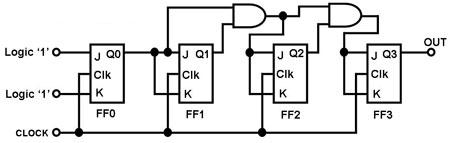
The circuit in Figure 1 is a 4-bit asynchronous counter, also known as a ripple counter. It consists of four J-K flip-flops with their J and K inputs connected to logic 1. This configuration causes the output of each...
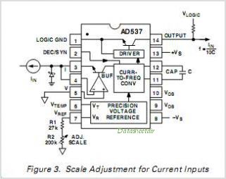
The AD650 is a voltage-to-frequency (V/F) and frequency-to-voltage (F/V) converter that offers high-frequency operation and low nonlinearity, features that were previously unavailable in a monolithic form. Its inherent monotonicity in the V/F transfer function makes the AD650 suitable for...