
digital counter circuits

The 4-bit asynchronous counter, or ripple counter, operates on the principle of sequential toggling of J-K flip-flops. In this configuration, the first flip-flop toggles its output state with each incoming clock pulse due to its J and K inputs being held high. This output then serves as the clock input for the next flip-flop, creating a cascading effect. Each subsequent flip-flop toggles based on the output of the previous one, resulting in a binary count that propagates through the flip-flops, hence the term "ripple." The counter counts up from 0 to 15 in binary (0000 to 1111) before resetting back to 0.
In contrast, the 4-bit synchronous counter achieves its counting mechanism through simultaneous clocking of all flip-flops. The first flip-flop still has its J and K inputs tied to logic 1, allowing it to toggle with each clock pulse. However, the second flip-flop's inputs are derived from the output of the first flip-flop, leading to a toggle rate that is half that of the first flip-flop. This pattern continues with each subsequent flip-flop being controlled by an AND gate that combines the outputs of the two preceding flip-flops, ensuring that the toggling continues at a halved rate, thus maintaining the binary counting sequence.
This synchronous design minimizes the propagation delay issues associated with asynchronous counters, making it more suitable for applications requiring precise timing and synchronization. The overall architecture of both counters illustrates fundamental principles of digital electronics, particularly in the use of flip-flops for counting and state storage.The circuit in Figure 1 is that of a 4-bit asynchronous counter, also known as a `ripple counter`. It consists of 4 J-K flip-flops whose J and K inputs are tied to logic `1`. This connection causes the output of each J-K flip-flop to toggle every time it gets a clock pulse. By using the output of the previous flip-flop to clock the next flip-flop, a `rippling` effect is achieved causing the flip-flops to count in binary fashion. The circuit in Figure 2 is that of a 4-bit synchronous counter. It consists of 4 J-K flip-flops, all of which are clocked at the same time, hence the name `synchronous counter`. Thus, the toggling of the output of the flip-flops in this counter depends on the states of their J and K inputs.
Recall that the J-K flip-flop`s output will only toggle when both J and K are `high`. The first flip-flop (lease-significant bit) of a synchronous counter has its J and K inputs directly tied to logic `1`. This causes its output to toggle automatically every time it gets a clock pulse. The second flip-flop`s J and K inputs are directly tied to the output of the first flip-flop. Thus, even if they get clocked at the same time, the second flip-flop will only toggle half the times as the first one.
The subsequent flip-flops` J and K inputs are tied to an AND gate whose inputs are tied to the outputs of the last two flip-flops before it. This ensures that each of these flip-flops will toggle at half the rate as the flip-flop before it, even if they are all clocked at the same time.
🔗 External reference
Related Circuits
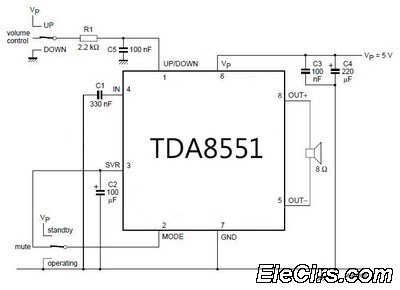
An amplifier with digital volume control can be designed predictably due to the simplicity of the circuit, which utilizes a single chip, the TDA8551. This series of mini amplifiers with digital volume control operates as a BTL (Bridge-Tied Load)...
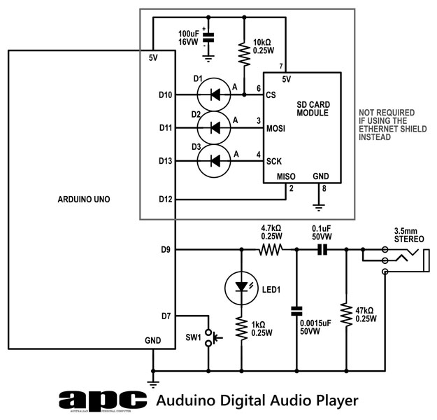
In this series, a diverse exploration of how Arduino interacts with various real-world devices has been presented, from servo motors to ultrasonic range finders, TVs to humidity sensors. The focus now shifts to generating sound using Arduino. The project...
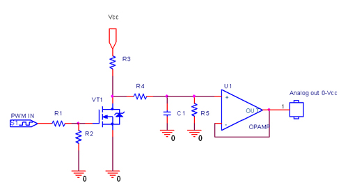
In electronics, a digital-to-analog converter (DAC or D-to-A) is a device that converts a digital code, typically in binary format, into an analog signal, which can be in the form of current, voltage, or electric charge. DACs are utilized...
This circuit measures the distance covered during a walk. The hardware is housed in a small box that can be slipped into a pants pocket, and the display is arranged as follows: the leftmost display (D2) represents kilometers (0...
This type of converter is used to convert analog voltage to its corresponding digital output. The function of the analog-to-digital converter is exactly opposite to that of a digital-to-analog converter. Like a digital-to-analog converter, an analog-to-digital converter is also...
Maxim has introduced a series of five integrated oscillator building blocks in the MAX260x series, covering a frequency range of 45 to 650 MHz. The MAX2606 is designed for the VHF band, allowing frequency variation of approximately ±3 MHz...