
1 KHz Frequency Wien Bridge Oscillator

The Wien Bridge Oscillator is a type of electronic oscillator that generates sine waves. It is notable for its ability to produce low-frequency signals with high stability and low distortion. The fundamental operation of the Wien Bridge Oscillator is based on a bridge circuit that includes resistors and capacitors, providing a precise frequency determination.
The core of the circuit consists of four resistors and two capacitors arranged in a bridge configuration. The resistors are typically labeled R1, R2, R3, and R4, while the capacitors are labeled C1 and C2. The bridge is balanced when the ratio of the resistances and capacitances satisfies the condition for oscillation. The frequency of oscillation can be calculated using the formula:
\[ f = \frac{1}{2\pi R \sqrt{C1 \cdot C2}} \]
where \( R \) is the resistance value that is typically equal for R1 and R2, and R3 and R4, while C1 and C2 are the capacitances.
To initiate oscillation, a gain element, usually an operational amplifier (op-amp), is employed. The gain of the op-amp is adjusted using a variable resistor (often referred to as a light bulb or thermistor in classic designs) to maintain the oscillation. This automatic gain control is crucial as it stabilizes the amplitude of the output sine wave, preventing distortion and ensuring consistent performance over time.
In practical applications, the Wien Bridge Oscillator is utilized in various fields, including audio signal generation, function generators, and testing equipment. Its simplicity and effectiveness make it a popular choice among engineers and hobbyists for generating sine wave signals in low-frequency applications. Proper layout and component selection are essential to minimize noise and ensure the fidelity of the generated waveform.The circuit was designed to create an electronic oscillator known as Wien Bridge Oscillator which can be used for the creation of low frequency sine wave. 🔗 External reference
Related Circuits
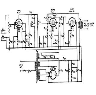
The signal from a microphone is too weak for a standard line input. This low-noise DC-coupled microphone amplifier provides a solution for anyone who wants to connect a microphone to a high-fidelity installation. As shown in the schematic diagram,...
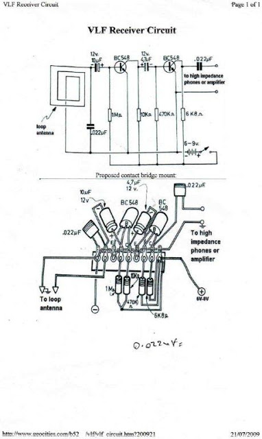
Low frequencies predominantly cover Earth's atmosphere. This range of frequencies can be produced by various unknown and unusual sources. A Very Low Frequency (VLF) sensor equipment can be developed to detect these frequencies for investigating the intriguing secrets hidden...
Today, it is no longer necessary to use discrete components for constructing oscillators. Many manufacturers now offer ready-made voltage-controlled oscillator (VCO) integrated circuits (ICs) that require only a few external components to determine the frequency. An example of such...
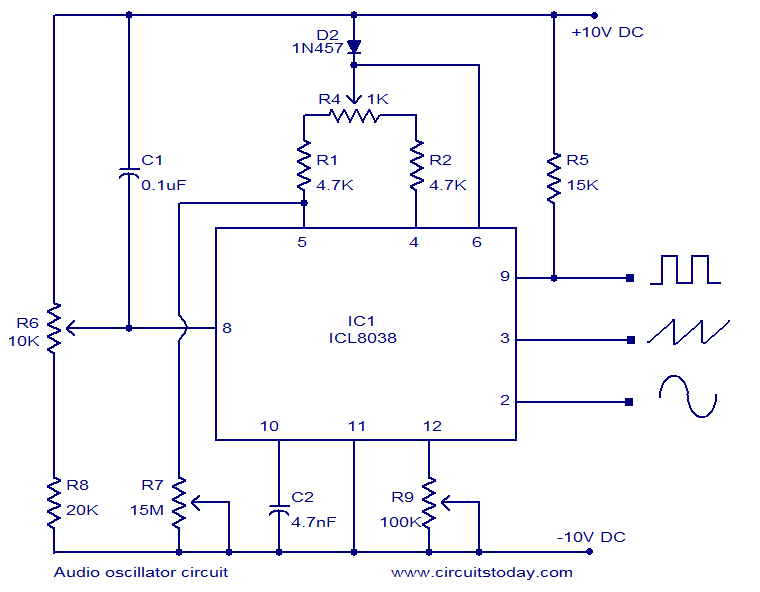
ICL8038-based audio oscillator circuit. Simultaneous sine, triangle, and square waveforms. Dual supply operation. Covers the full audio frequency range. The ICL8038 is a precision waveform generator integrated circuit that can produce sine, triangle, and square waveforms simultaneously. This versatility makes...
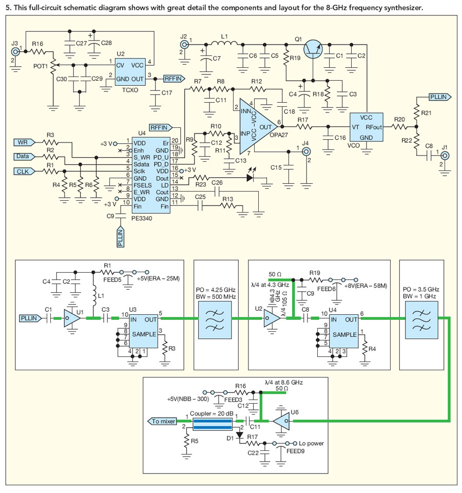
By developing a low-noise frequency synthesizer at 2 GHz and applying a pair of doublers, it is possible to achieve low-phase-noise outputs past 8 GHz for digital microwave radios. The design of a low-noise frequency synthesizer operating at 2 GHz...
One example of the phase shift oscillator is the Bubba oscillator. This oscillator achieves a 45-degree phase shift for each section from a quad op-amp package. The Bubba oscillator is a type of phase shift oscillator that utilizes a...