
microphone amplifier 20khz 12v

The microphone amplifier circuit is designed to enhance weak microphone signals, making them suitable for connection to standard line-level inputs found in audio equipment. The core of the design is the differential amplifier configuration, which employs a low-noise dual transistor (T1, T-03E). This transistor configuration ensures minimal noise introduction while effectively amplifying the input signal.
The constant-current source, formed by the combination of transistor T2 and LED D1, is crucial for maintaining a stable operating point for the input stage. This configuration ensures that the input stage operates consistently, providing reliable amplification over varying input signal conditions.
The operational amplifier (OP-270E) plays a significant role in the circuit, as it amplifies the differential signal obtained from the collectors of the dual transistor. With a bandwidth extending from 1 Hz to 20 kHz, the amplifier is well-suited for audio applications, ensuring that the full spectrum of audio frequencies is captured with minimal distortion. The specified distortion level of less than 0.005 percent within the audio range indicates high fidelity, making this amplifier suitable for professional audio applications.
The design also allows for efficient use of components; since only one half of the OP-270E is utilized in this configuration, the remaining half can be repurposed for additional functionality, such as in a stereo amplifier setup. The power supply requirements are flexible, allowing operation from a symmetrical supply voltage of ±12 V to ±15 V. This compatibility with commonly available supply voltages enhances the practicality of the circuit, making it accessible for integration into various audio systems. Overall, this microphone amplifier circuit is an effective solution for enhancing microphone signals, providing high-quality audio performance in a straightforward design.The signal from a microphone is two weak for a standard line input. This low-noise DC-coupled microphone amplifier provides a solution for anyone who wants to connect a microphone to his or her hi- installation. As can be seen from the schematic diagram, a good circuit does not have to be complex. A differential amplifier is built around T1 (MA T-03E), which is a low-noise dual transistor. The combination of T2 and LED D1 forms a constant-current source for the input stage. A low-noise opamp (OP-270E) amplifies the difference signal that appears at the collectors of the dual transistor. The result is an analogue signal at line level. Using Operational amplifier The bandwidth of the amplifier ranges from 1 Hz to 20 kHz. Within the audio range (20 Hz to 20 kHz), the distortion is less than 0. 005 percent. Since only half of the OP-270E is used, the remaining opamp could be used in the output stage of a stereo version.
The amplifier can be powered from a stabilized, symmetrical supply with a voltage between ±12 V and ±15 V. Such supply voltages are already present in many amplifier. 🔗 External reference
Related Circuits
This circuit diagram illustrates the conversion of a speaker into a microphone. When sound waves impact the diaphragm of a speaker, fluctuations occur in the coil, generating an induced voltage. This induced voltage is typically substantial but low in...
A 6-watt audio amplifier circuit utilizing the TDA2613 is presented here. The TDA2613 is an integrated Hi-Fi audio amplifier IC produced by Philips Semiconductors. The IC is designed for high-quality audio amplification. The circuit features the TDA2613 IC, which is...
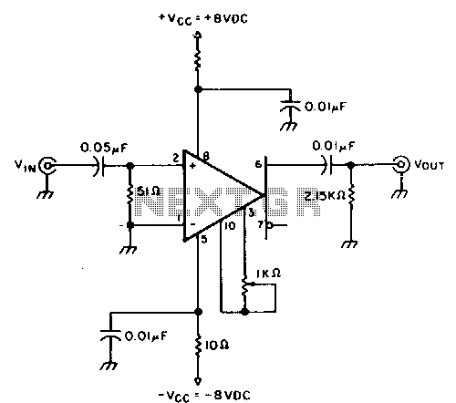
This circuit provides approximately 20 dB of voltage gain with a frequency range from 0.5 to 50 MHz. The low-frequency response of this circuit can be extended by increasing the value of the 0.05 µF capacitor or by removing...
This circuit is very basic to build and puts out great power for your car or home. Keep all leads as short as possible. This circuit is designed to deliver substantial power output suitable for automotive or residential applications. The...
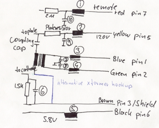
The M7 capsule features a center-terminated, dual-diaphragm design and supports three polar patterns. A switch on the power supply allows for the selection of Cardioid, Figure-of-8, or Omnidirectional patterns. The amplifier circuit is reminiscent of Gefell's historical models, the...
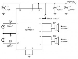
The provided schematic represents a car stereo amplifier circuit that can be utilized in cars or other vehicles. The circuit is based on the TDA1553, which is a Class-B audio amplifier. This circuit is straightforward, consisting solely of the...