
1-Ma Current Sink

In this circuit configuration, the operational amplifier (op-amp) is utilized to maintain a constant current through a load connected to the collector of transistor Q1. The grounding of the non-inverting terminal establishes a reference point for the op-amp, ensuring that it operates in a linear region. The negative feedback path from the emitter of Q1 to the inverting terminal of the op-amp is crucial for regulating the output voltage and, consequently, the current flowing through the load.
The voltage across resistor R1, which is connected in series with the load, is monitored to provide feedback to the op-amp. Given that the voltage at the inverting terminal is approximately 0.55 V, this indicates that the op-amp is configured to maintain a specific output voltage level. The relationship between the voltage across R1 and the current through it can be described using Ohm's Law, where the current I through R1 can be expressed as I = V/R. In this case, with a fixed voltage of approximately 0.55 V, and assuming R1 is appropriately sized, a constant current of about 1 mA is established.
This configuration is commonly used in applications where a stable current is required for driving loads such as LEDs, sensors, or other electronic components. The stability of the current is a result of the feedback mechanism, which continuously adjusts the output of the op-amp to counteract any variations in load conditions, ensuring reliable operation across different scenarios. The choice of components, including the characteristics of Q1 and R1, plays a significant role in determining the overall performance and efficiency of the circuit. A fixed current flows through any load that is connected between the positive supply and Ql"s collector. The noninverting terminal of the op amp is grounded, and negative feedback flows between the output of the circuit (Ql"s emitter) and the inverting terminal. The voltage across Rl is thus equal to the voltage at the inverting terminal (approximately 0.55 V), so a fixed current of about 1 mA flows through the load, Ql"s emitter, and Rl.
Related Circuits
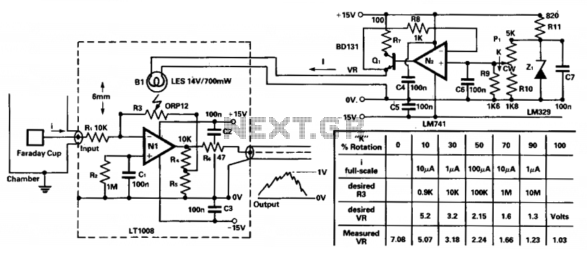
To amplify small current signals, such as those from an electron collector inside a vacuum chamber, it is beneficial for reasons related to noise and bandwidth to utilize a "head amplifier" connected to the chamber. The operational amplifier N1...
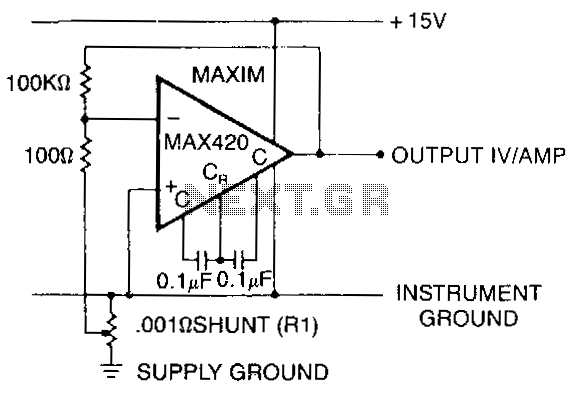
This circuit measures the power supply current of a circuit without using a current shunt resistor: R1 is only 3 cm of #20 gauge copper wire. A length of the power distribution wiring can be used for R1. The...
Current loop analog data transmission is utilized in industrial environments due to its robustness, offering good noise immunity and the capability for wiring fault detection. Current loop analog data transmission systems are widely employed in industrial applications due to their...
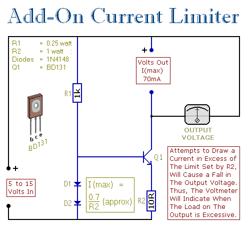
This circuit allows you to set a limit on the maximum output current available from your PSU. It's very useful when you power-up a project for the first time or carry out a soak-test. By setting an upper limit...
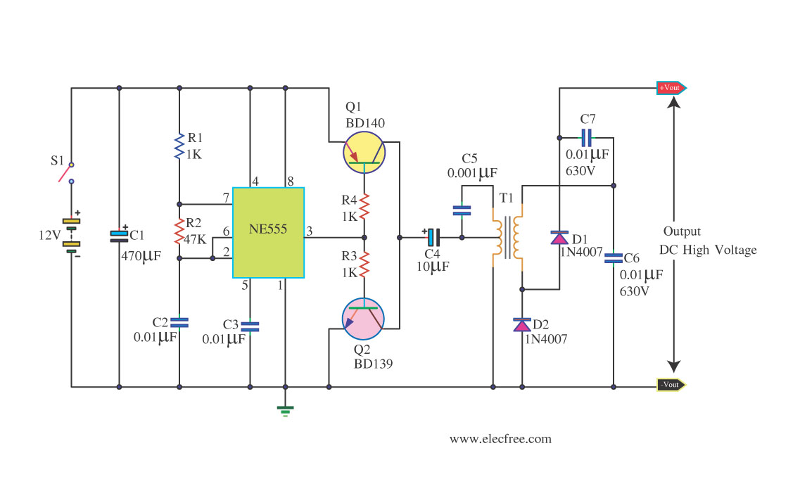
This circuit is a DC to DC inverter that can convert a 12V DC battery voltage to a high voltage of 300V DC. This circuit operates with low current. This DC to DC inverter circuit is designed to efficiently step...
This PSU has been especially designed for current-hungry ham radio transceivers. It delivers safely around 20Amps at 13.8V. For lower currents, a separate current limiting output, capable of 15ma up to a total of 20A has been added. The...