
An Add-on Current Limiter

The current limiting circuit is designed to provide a safeguard against excessive current draw from a power supply unit (PSU), which can potentially damage both the PSU and connected devices. The circuit typically consists of a current sensing resistor, an operational amplifier (op-amp), and a control element such as a transistor or a relay.
In operation, the circuit monitors the output current flowing through the load. The current sensing resistor is placed in series with the load, and the voltage drop across this resistor is proportional to the current flowing through it. This voltage drop is fed into the input of the op-amp configured as a comparator. The op-amp compares the sensed voltage with a reference voltage, which can be adjusted to set the desired maximum current limit.
When the output current exceeds the set limit, the op-amp output switches states, activating the control element. If a transistor is used, it may be configured in such a way that it reduces the output voltage or completely shuts off the output to the load. In the case of a relay, it may disconnect the load from the power supply.
This circuit is particularly beneficial during the initial power-up of electronic projects, where inrush currents can be significantly higher than normal operating currents. Additionally, during soak tests, where devices are subjected to prolonged operation under various conditions, the circuit helps prevent damage due to unexpected current surges.
Overall, implementing a current limiting circuit is an effective way to enhance the reliability and safety of electronic designs, ensuring that both the power supply and connected devices are protected from adverse conditions.This circuit allows you to set a limit on the maximum output current available from your PSU. It`s very useful when you power-up a project for the first time - or carry out a soak-test. By setting an upper limit on the current available from your PSU - you can protect both your power supply - and any device connected to it. 🔗 External reference
Related Circuits
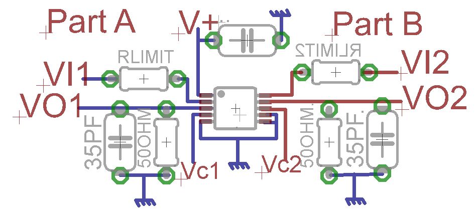
A request for advice regarding the connection diagram of the MAX4685 analog switch is presented. The circuit involves two inputs, VI1 and VI2. The MAX4685 is a low-voltage, dual analog switch designed for low on-resistance and high-speed switching applications. In...
This is an adjustable constant current regulator circuit. This circuit can be used in a bench power supply to prevent the circuits that are tested from being damaged. The adjustable constant current regulator circuit is designed to provide a stable...
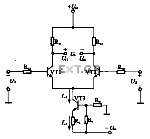
A constant current source is utilized in the differential amplifier circuit, which includes an emitter resistor. In this configuration, an increase in the output voltage (Ua) is not desirable. To ensure that Ua remains stable, the supply voltage (Ucc)...
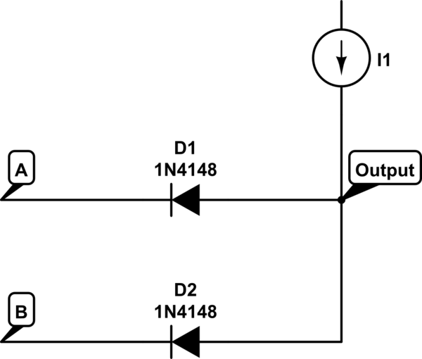
The voltage at the anode and cathode of the diodes is checked to determine whether they are conducting. There is confusion regarding the current source and how to determine the state of the diodes for input combinations (00, 01,...
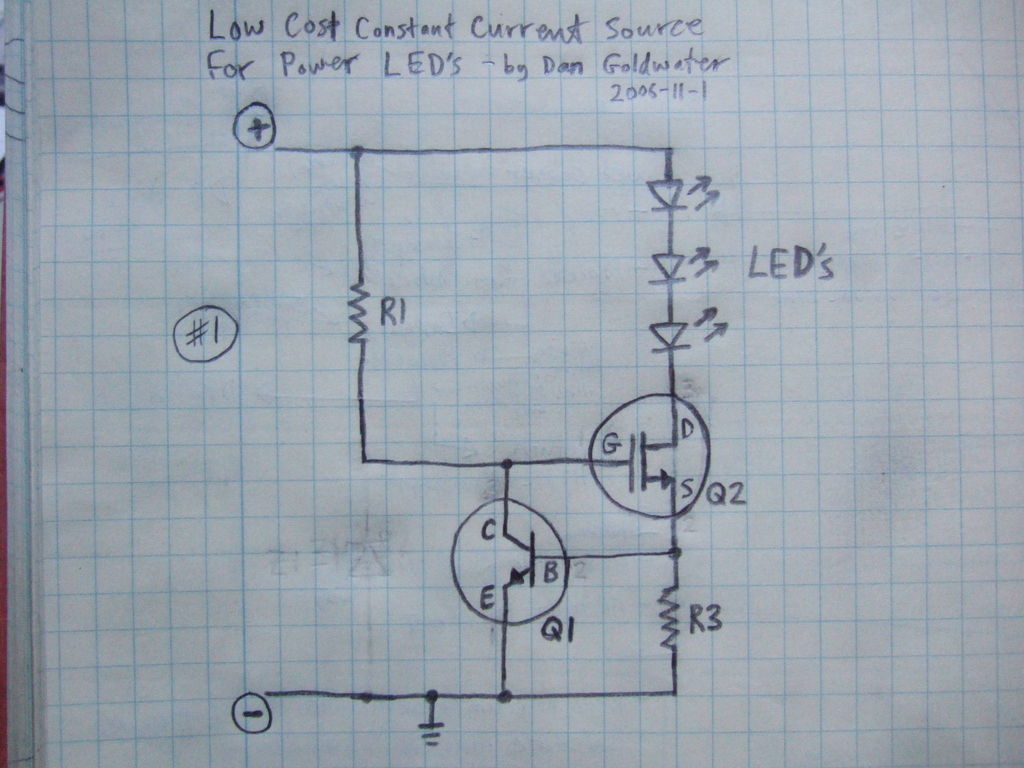
Here is a simple and inexpensive ($1) LED driver circuit. The circuit functions as a constant current source, ensuring that the LED maintains consistent brightness. The LED driver circuit is designed to provide a stable current to the LED, which...
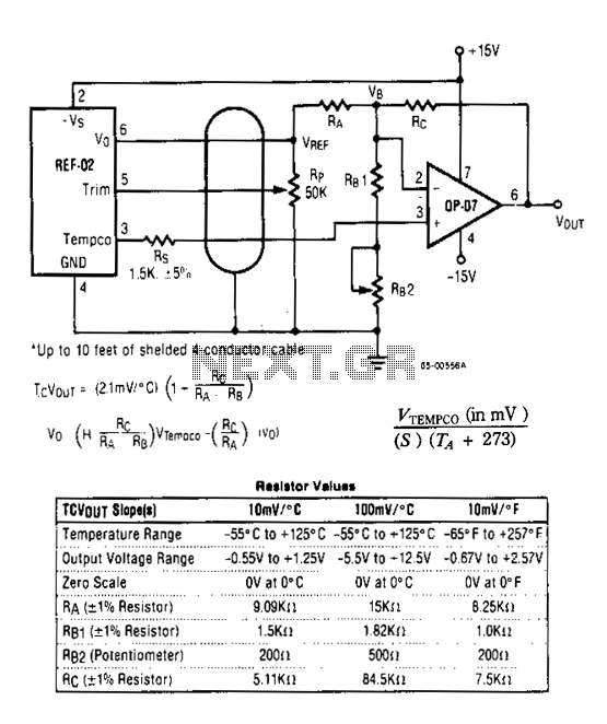
The DVM-to-temperature adapter is constructed around a single integrated circuit (IC), the National LM10. This micropower IC features a stable 0.2 V reference, a reference amplifier, and a general-purpose operational amplifier. The circuit is designed to operate within a...