
1 watt PLL portable fm transmitter circuit

This portable FM transmitter is designed for ease of use and efficient performance in transmitting audio signals over FM frequencies. The integration of a limiter ensures that the audio signal remains within acceptable amplitude levels, preventing distortion during transmission. The microphone amplifier allows for direct input of audio signals, making it suitable for various applications, including personal broadcasting and educational demonstrations.
The PLL (Phase-Locked Loop) section is crucial for maintaining frequency stability and accuracy. By allowing for digital tuning, it simplifies the process of selecting the desired transmission frequency. The division of the schematic into three distinct sections facilitates troubleshooting and understanding of the circuit's operation. The RF section handles the modulation and amplification of the radio frequency signal, while the audio section processes the input audio signal.
To operate the transmitter effectively, the user must connect a 6 V / 0.1 A bulb to provide visual feedback of the RF power output. By setting the RF power to high, the transmitter is activated, and tuning must be performed on a receiver to ensure proper reception of the transmitted signal. Adjustments to the L1 coils may be necessary to achieve optimal tuning, and the position of L1 should be fixed when the tuning voltage at Q3 falls within the specified range of 4-9 V.
Capacitors C15, C16, and C17 play a vital role in fine-tuning the transmitter's output power. Their values can be adjusted to maximize the brightness of the bulb, indicating the highest power output achievable. The final steps involve connecting an appropriate antenna and audio source, with resistor R1 being adjusted to balance the audio output level, ensuring it matches the loudness of other stations. This careful calibration allows for a clear and effective transmission of audio signals over FM frequencies.This Simple Portable FM transmitter includes a limiter, a microphone amplifier and a PLL digital tuning. All the components are placed on one circuit board. The RF power is switchable between 1 W (HI) and 0, 2 W (LO). The schematic diagram is split into 3 parts: RF part (numbered from 1), PLL (numbered from 30) and audio part (numbered from 50).
Co nnect a 6 V / 0, 1 A bulb to the output and set the correct frequency on PLL. Set the RF power to HI. currently activate the transmitter. you must tune it on a receiver. perhaps you may stretch coils of the L1. Fix the L1 in position when the tuning voltage (on Q3) is in range 4-9 V. Then use C15, C16 and C17 to regulate the best power (the highest light of the bulb). Then you`ll be able to connect antenna and audio signal. change R1 till the audio sounds as loud because the alternative stations. 🔗 External reference
Related Circuits
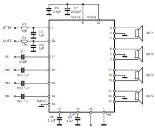
The TDA7383 features a fully complementary PNP/NPN output configuration, enabling a rail-to-rail output voltage swing without the need for bootstrap capacitors. This design significantly reduces the component count, allowing for compact assemblies. An integrated clipping detector facilitates gain compression...
The following circuit illustrates a Single Supply Phase Locked Loop Circuit Diagram. This circuit is based on the LM331 integrated circuit. Features include the response of... The Single Supply Phase Locked Loop (PLL) circuit utilizing the LM331 integrated circuit is...
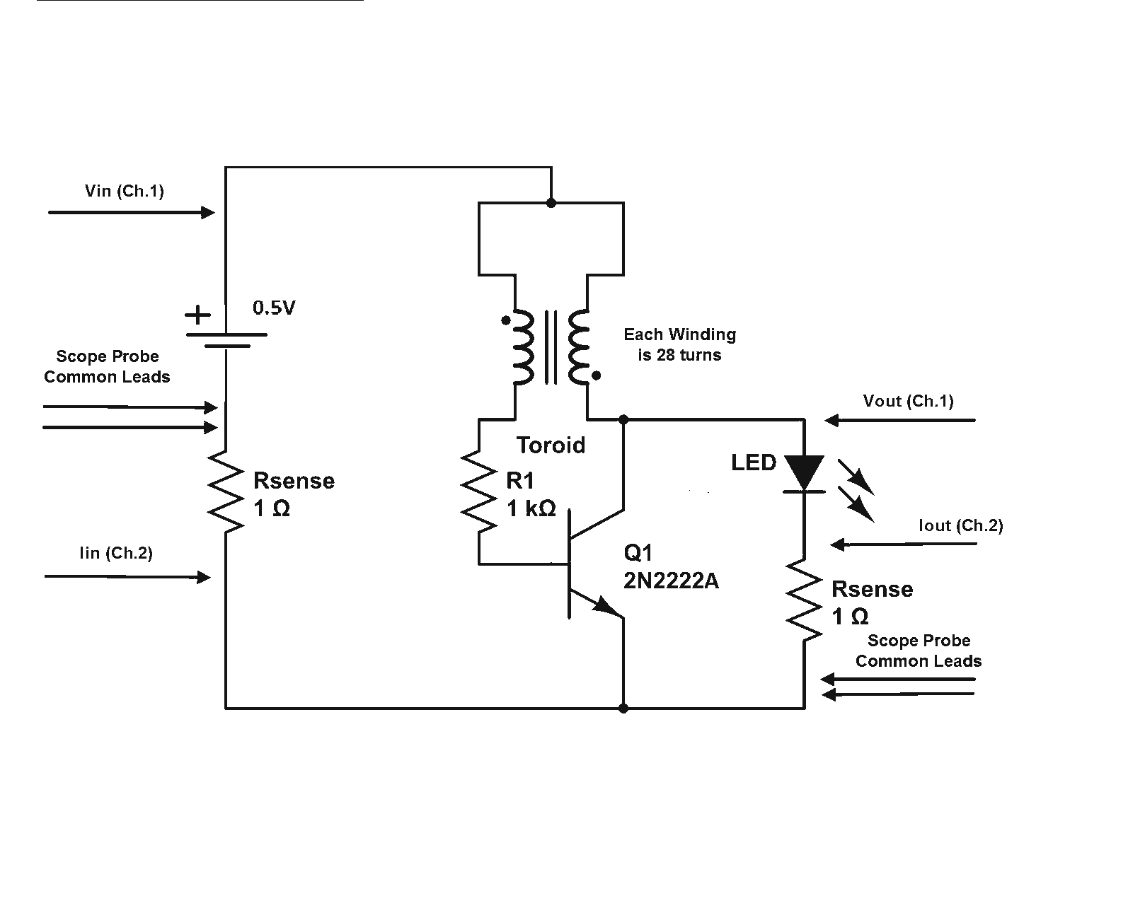
Is a Joule Thief circuit capable of achieving overunity? Joule Thief schematic including scope measurement points. The Joule Thief is a minimalist circuit designed to extract energy from low-voltage sources, such as depleted batteries, and convert it into a usable...
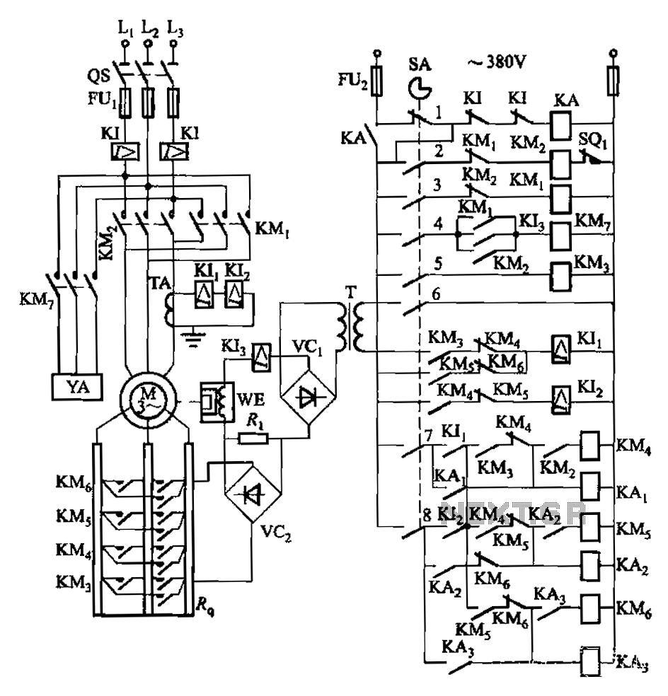
Attached to the wall is a high-rise building construction elevator, an essential piece of vertical transportation machinery. Its drive motor is typically a wound wire induction motor. The main switch and eddy current brake controls are also mounted on...

A Countdown Timer Circuit is a project submitted by a group of students for their ECE 130 - Computer Application class on August 31, 2006, at the University of St. La Salle, Philippines. The seven-segment decoder is utilized in...
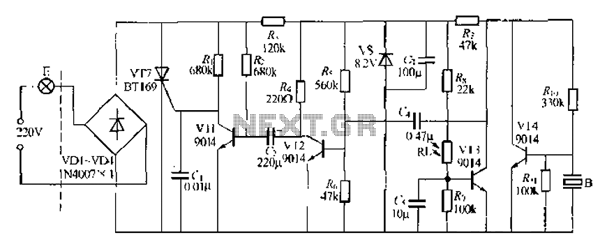
A modified piezoelectric ceramic acoustic-electric transducer is utilized to create a sound and light control system for a stairway walkway with a delay lighting switch. The circuit structure is relatively simple, consisting of diodes VD1 to VD4 and a...