
Joule thief circuit gets overunity

The Joule Thief is a minimalist circuit designed to extract energy from low-voltage sources, such as depleted batteries, and convert it into a usable output voltage. It operates on the principle of inductive energy transfer and is often employed in applications requiring energy efficiency. The circuit typically consists of a few essential components: a transistor, a resistor, a toroidal inductor, and a diode.
In a standard Joule Thief configuration, the transistor acts as a switch that rapidly turns on and off, allowing current to flow through the inductor. As the current builds up in the inductor, it stores energy in its magnetic field. When the transistor is turned off, the magnetic field collapses, and the inductor generates a high voltage spike, which is directed to the load through the diode. This process enables the Joule Thief to boost the voltage from a low source, making it possible to power devices that require a higher voltage than what is available from the battery.
Scope measurement points in the Joule Thief circuit are crucial for analyzing the performance and efficiency of the circuit. These points typically include the voltage across the load, the voltage at the collector of the transistor, and the current flowing through the circuit. By monitoring these parameters with an oscilloscope, one can observe the switching behavior of the transistor, the characteristics of the voltage spike generated by the inductor, and the overall efficiency of energy conversion.
The concept of overunity, or achieving more energy output than input, is often discussed in relation to the Joule Thief. However, it is essential to note that according to the laws of thermodynamics, achieving true overunity is not feasible. The Joule Thief can improve energy extraction from low-voltage sources, but it does not generate energy from nothing; rather, it optimizes the use of available energy.Is a joule thief circuit gets overunity? Joule Thief Schematic Including scope measurement points. 🔗 External reference
Related Circuits
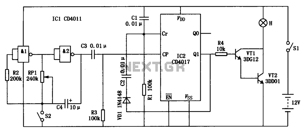
A touch dimmer circuit is illustrated in the accompanying diagram. It utilizes a finger touch control piece to enable the turning on, off, or stepless adjustment of incandescent lighting. This circuit is applicable in dimming filament lamps and for...

This is a simple circuit that can be used as a sequential signal light in automobiles. The circuit is based on two integrated circuits (ICs): a TS 555 CN CMOS timer IC and a CD4017 decade counter IC. The...
This is not a sophisticated automatic keyer but it is lot QRP to build and to have fun operating it. When the paddle is connected to the DOT terminal, C1 starts to charge. When C1's charge reaches sufficiently high value,...
The construction LED circuit illustrated in the figure requires manual power. Once powered, the light will blink to alert individuals to pay attention to safety. The circuit is designed to enhance safety awareness in construction environments by utilizing a blinking...
Transistors are configured as a Darlington pair in this circuit. A thermistor is utilized to detect or sense heat. A 12K variable resistor is employed to adjust the activation of the buzzer at the desired temperature. The operation of...
The following circuit illustrates a Video and DVD Modulator in a VHF/UHF electronic diagram. Features include an oscillator that utilizes a transistor for high-frequency operation. The video and DVD modulator circuit serves to convert video signals into a format suitable...