
10 Band Audio Equalizer

This audio equalizer circuit is designed to manipulate audio signals across ten distinct frequency bands, allowing for enhanced control over sound quality and tonal balance. The use of low-cost operational amplifiers (op-amps) contributes to the affordability and accessibility of the design while maintaining a professional standard of audio processing.
The core of the equalizer consists of a series of band-pass active filters, each tailored to a specific frequency range. These filters utilize op-amps configured in a feedback loop to achieve the desired gain and bandwidth characteristics. The design ensures that each band can be adjusted independently, facilitating precise equalization of audio signals.
U11, positioned at the input stage, functions as an attenuator. Its primary role is to adjust the amplitude of the incoming audio signal, ensuring that it is within an optimal range for processing by the subsequent equalization filters. This attenuation is crucial for preventing signal distortion and maintaining audio fidelity.
Following the filtering process, U13 serves as a final voltage amplifier. It boosts the level of the equalized audio signals before they are routed to the next stage of the audio processing chain. This amplification stage is essential for ensuring that the output signal is sufficiently strong to drive subsequent audio equipment without degradation in quality.
The power supply specifications for the circuit are critical for its operation. The positive voltage supply (VCC) is specified to be within the range of +12 to +15 VDC, while the negative voltage supply (VDD) operates between -12 to -15 VDC. This dual supply configuration is common in audio applications, as it allows the op-amps to handle both positive and negative portions of the audio waveform effectively.
Overall, this ten-band audio equalizer circuit exemplifies a robust design that balances cost and performance, making it suitable for both professional and amateur audio applications.This circuit allows you to equlize the audio signals in ten band. It uses low cost op-amps to form a professional equalizer circuit. The heart of the design is a classical band-pass active filter. The U11 acts as an attenuator to prepare the signal level for equlizing. The U13 acts as a final voltage amplifier to deliver the equlized audio signals to the next stage. The VCC is in range of +12 ~ +15 VDC and The VDD is in range of -12 ~ -15 VDC respectively. 🔗 External reference
Related Circuits
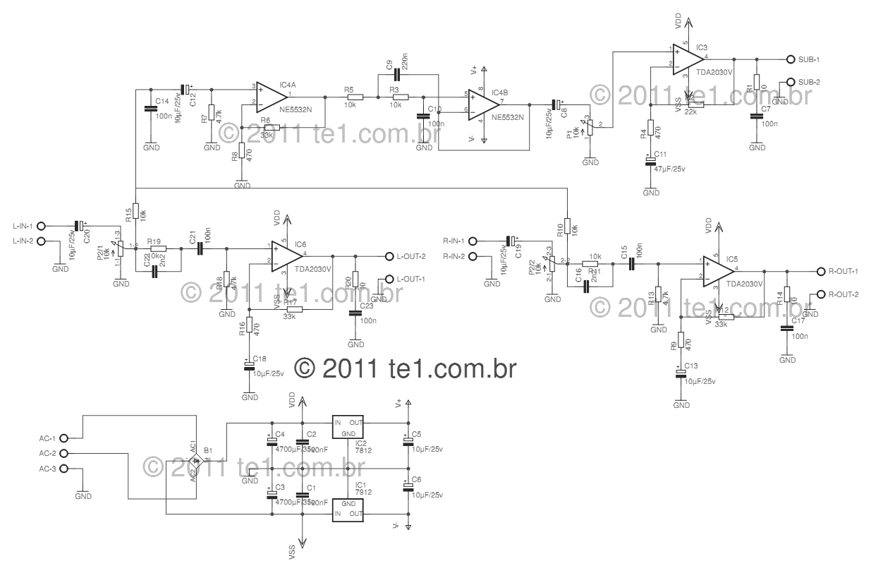
This circuit is a complete application for a 2.1 amplifier system, featuring two satellite speakers for TDA and one subwoofer. It is commonly used in commercial applications to enhance the audio output of computers using a stereo amplifier along...
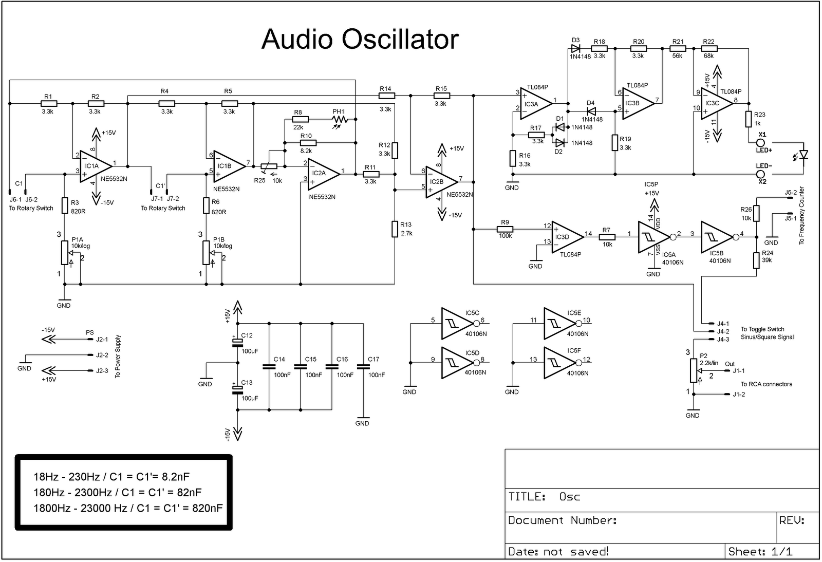
The project involves adding a DIY audio oscillator to a home workshop, which is essential for testing audio projects. While a basic oscillator is already available, it lacks a frequency counter. The design follows a schematic that provides a...
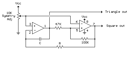
The circuit illustrates a straightforward triangle and square wave generator utilizing a common dual operational amplifier, the LM1558, capable of producing very low frequencies around 10 kHz. The time interval for one half-cycle is approximately determined by the product...
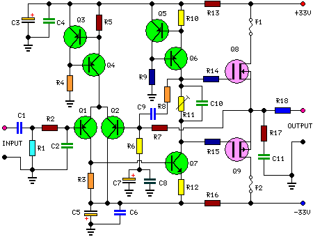
This is a 25 Watt basic power amplifier designed to be relatively easy to build at a reasonable cost. It offers better performance than the standard STK module amplifiers commonly used in nearly all mass-market stereo receivers manufactured today. The...
Several KE 4-211-2 Sennheiser microphones were utilized to create a device for acoustic signal analysis. These microphones are connected to a National Instruments data acquisition device via approximately 1 meter long cables, with a sampling rate set at 50...
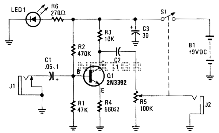
The amplifier's gain is nominally 20 dB. Its frequency response is determined primarily by the values of a few components, mainly C1 and R1. The schematic diagram values provide a response of ±3.0 dB from approximately 120 Hz to...