
audio Microphones disturbed by capacitance

The system consists of several key components: the KE 4-211-2 Sennheiser microphones, a National Instruments data acquisition device, and passive components including resistors and capacitors. The microphones convert acoustic signals into electrical signals, which are then transmitted through cables to the data acquisition device. The choice of a 1-meter cable length is appropriate for minimizing signal degradation, although it is essential to consider the cable's impedance characteristics.
The sampling rate of 50 kHz is suitable for capturing a wide range of audio frequencies, ensuring that the data acquisition system can accurately process the acoustic signals. However, the introduction of a resistor and capacitor creates a low-pass filter effect, which can inadvertently affect the frequency response of the system. The step function disturbance observed during data collection indicates a transient response caused by the sudden change in load impedance when the data acquisition device begins sampling.
When the data acquisition device is inactive, the capacitors in the circuit charge slowly, creating a stable DC offset. Upon activation of data collection, the rapid change in impedance can lead to an abrupt voltage change, manifesting as a step function in the output signal. This behavior can distort the intended frequency spectrum of the acoustic signals being analyzed.
To mitigate this issue, several strategies may be employed. First, ensuring that the input impedance of the data acquisition device matches the output impedance of the microphone circuit can help reduce the impact of impedance mismatch. Additionally, implementing a buffer amplifier between the microphones and the data acquisition device can isolate the microphone output from the input load, thereby maintaining a more stable signal during data collection.
Furthermore, examining the values of the resistor and capacitor in the low-pass filter configuration may provide insight into optimizing the filter's cutoff frequency. Adjusting these values can help minimize the distortion while preserving the desired acoustic signals. Lastly, it may be beneficial to implement a pre-conditioning circuit that stabilizes the signal before it reaches the data acquisition device, ensuring that the system operates effectively under varying conditions.Used several KE 4-211-2 Sennheiser microphones to assemble a device for acoustic signal analysis. They are connected to a National Instruments data acquisition device with ~1 m long cable and sampling rate is set to 50kHz. I`ve added a resistor and a capacitor as described here (2nd page). However after a start of data collection instead of clear acoustic signal I get strong disturbance looking like a step function
in low pass filter. It obviously distorts my frequency spectrum. After investigation I found out that when NI device is not collecting data, capacitors charge slowly and start of collection probably results in dramatic drop of impedance on inputs. What might be a reason for this behavior and what should I do to make it work properly 🔗 External reference
Related Circuits
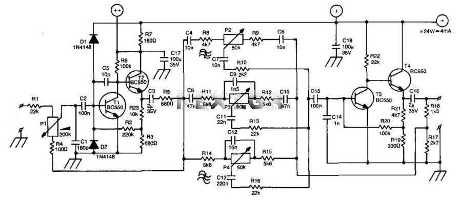
A line amplifier is a valuable component for matching line signals or increasing their levels. This functionality is essential during recording sessions or in public-address systems. Additionally, multiple line amplifiers can be combined to create a line mixer. The amplifier's...

Proper grounding is essential for eliminating hum and ground loops. The ground connections for J1, P1, C2, C3, and C4 should all be connected to the same point. Additionally, connect C9 to the output ground. In electronic circuits, grounding serves...
Designs for audio amplifiers with DC coupling to the load are not frequently seen today, despite offering distinct advantages. Audio amplifiers that employ DC coupling to the load provide several benefits that can enhance performance in specific applications. In traditional...
This project is also an essential part of the expandable analyser to be published soon or perhaps eventually, and one meter circuit is used for each frequency band. There are many other uses for a simple LED VU meter....
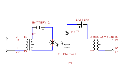
This circuit transmits audio information using light waves. It employs amplitude modulation (AM) to vary the intensity of an LED, which is detected by a cadmium sulfide photocell that changes its resistance based on light intensity. The circuit includes...

This high-power audio amplifier provides top-quality performance for loudspeakers with an impedance of 4 to 8 ohms. It operates within a frequency range of 20 to 20,000 Hz and requires a voltage supply of 24 to 36 volts, with...