
10 Watt CB Linear amplifier

L1 matches a 50-Ohm input to the 10-Ohm input impedance of TR1. The output of TR1 is coupled via T1 to TR2 and TR3 bases. T1 also transforms the impedance to the very low input impedance of these two transistors, so the secondary winding must be quite thick wire.
TR2 and TR3 amplify the signal even further, up to about 12-Watts. They are in a push-pull configuration so T1 secondary and T2 primary must both be symmetrical. T2 increases the output impedance to 50-Ohms.
TR1, TR2 and TR3 all have a 330R and 10n between the collector and base terminals. This is needed for stability and is a crude form of neutralising. Without these components then the stages would almost certainly oscillate or generate spurious signals. An additional 180pf capacitor from both TR2 and TR3 collectors to ground (not shown in the circuit diagram) give the amplifier an even cleaner output signal. The 68pf capacitor across the output may be increased if you never use the 30MHz band. It, too, increases the stability and helps to keep the harmonic content low. My spectrum analyser did not show any significant spurious or harmonic outputs from 0 - 100MHz when driven at 10-watts continuous, 14MHz. All spurious outputs were better than -60dBm (-70dBc), which I thought was pretty good!
TR4 is nothing more than a high-current constant voltage series regulator using a 3v3 Zener diode for stability. It provides the base-bias voltage for TR2 and TR3. The 1K thermistor is thermally coupled to the tinned-copper heatsink to reduce the bias a little when the PA gets hot. More about the thermistor later.
Alignment
To align, set the 1K0 potentiometer to minimum resistance, apply power to the 'PA-12v' and 'DV-12v' terminals whilst monitoring the current drawn by the 'PA-12v' connection. The current should be next to nothing. Increase the potentiometer until the current rises to about 50 - 100 mA. That's it!
Coils
I invariably receive loads of e-mail asking me all about the coils I use. "What was the relative humidity when you wound ..." and "I don't understand what a ferrite bead looks like ...". Ok, so to answer your questions:
L1 is 6 + 6 turns 28 - 36 SWG wire on two "small" ferrite beads super-glued together - side-by-side. The two windings are connected in series to form a single 12-turn coil with a centre-tap. The two ends of the coil are input to the amplifier and ground. The centre-tap is connected to TR1 BASE via a capacitor.
The described linear amplifier circuit is designed to provide a significant output power of 10 watts, with capabilities exceeding 15 watts into a 50-ohm load. The use of common plastic transistors, often found in CB radios, allows for cost-effective construction. The key transistor in the design is the 2SC2078, although alternatives such as TIP31, TIP41, TIP3055, or MJE3055 can be utilized for the bias generator (TR4), provided they can handle up to 1 Ampere and fit within a TO220 package.
The amplifier supports a wide frequency range, from 1.8 MHz to over 30 MHz, with varying drive levels depending on the frequency. A minimal drive of 2-5 mW is sufficient for frequencies below 14 MHz, while 10 mW is required at 30 MHz. This makes it suitable for QRP (low-power) applications, allowing for the construction of a simple CW rig using only a crystal oscillator and the amplifier.
The circuit topology includes a matching network (L1) that adapts the 50-ohm input to the 10-ohm input impedance of TR1. The output stage employs a push-pull configuration with transistors TR2 and TR3, which further amplify the signal to approximately 12 watts. The transformer (T1) plays a critical role in impedance transformation and coupling, necessitating robust construction with thick wire for the secondary winding to handle the low input impedance of the output transistors.
Stability is enhanced through the inclusion of a 330-ohm resistor and a 10 nF capacitor between the collector and base terminals of TR1, TR2, and TR3. This configuration mitigates the risk of oscillations and spurious emissions. Additional capacitors, such as a 180 pF capacitor from the collectors of TR2 and TR3 to ground, further refine the output signal quality. The output capacitor (68 pF) can be adjusted based on the frequency usage, enhancing stability and reducing harmonic content.
The biasing for TR2 and TR3 is managed by TR4, a voltage regulator utilizing a 3.3V Zener diode for stability. A thermistor is thermally coupled to the heatsink to adjust biasing as the amplifier heats up, preventing thermal runaway.
Alignment of the amplifier is straightforward; it involves adjusting a 1K potentiometer while monitoring the current drawn by the amplifier to achieve the desired operating point.
The coil design for L1 consists of 12 turns of wire wound on two ferrite beads, configured to create a center-tap connection for input to the amplifier. This construction method aids in achieving the necessary inductance and performance characteristics for the amplifier's operation.
Overall, this amplifier design represents a practical solution for achieving higher power levels in amateur radio applications while maintaining a focus on simplicity and cost-effectiveness.It is quite easy to get a watt or more with very simple equipment, but to get more than 5 watts becomes a little more difficult. This article describes a 10 watt linear amplifier that is capable of delivering over 15 watts into 50 ohms and uses cheap plastic transistors that are used in CB equipment.
If you have difficulty in finding 2SC2078 then lift the lid of your CB set to find a suitable alternative. The bias generator transistor, TR4, is marked TIP31 in the circuit diagram, but here you can use just about anything that will fit.
You could even use another 2SC2078, if you had money to burn, but more practical components would be TIP41, TIP3055, MJE3055. All that matters is that it will pass up to 1 Ampere and have the correct base details in a TO220 case.
The amplifier has a wide bandwidth, from 1.8 MHz through to over 30 MHz. The drive level required is only about 2 - 5 mW under 14 MHz, rising to 10 mW at 30 MHz. You can therefore make a good QRP CW rig with nothing more than this PA and a simple crystal oscillator. I can achieve 12 watts out of mine using a 10-turn loop around my Grid Dip Oscillator! I can get over 15 watts from my Marconi signal generator, but above about 12 watts it is being over-driven an may not be very nice to look at on the spectrum analyser.
The circuit was designed to be as clean as possible. The circuit was originally designed to accompany my phasing-type SSB exciter, but it can be used to amplify almost any HF signal from 2mW in the HF band. Note that there is needed a Low-Pass filter between the amplifier and antenna. This is a requirement for ALL transmitters. L1 matches a 50-Ohm input to the 10-Ohm input impedance of TR1. The output of TR1 is coupled via T1 to TR2 and TR3 bases. T1 also transforms the impedance to the very low input impedance of these two transistors, so the secondary winding must be quite thick wire.
TR2 and TR3 amplify the signal even further, up to about 12-Watts. They are in a push-pull configuration so T1 secondary and T2 primary must both be symetrical. T2 increases the output impedance to 50-Ohms. TR1, TR2 and TR3 all have a 330R and 10n between the collector and base terminals. This is needed for stability and is a crude form of neutralising. Without these components then the stages would almost certainly oscillate or generate spurious signals. An additional 180pf capacitor from both TR2 and TR3 collectors to ground (not shown in the circuit diagram) give the amplifier an even cleaner output signal.
The 68pf capacitor across the output may be increased if you never use the 30MHz band. It, too, increases the stability and helps to keep the harmonic content low. My spectrum analyser did not show any significant spurious or harmonic outputs from 0 - 100MHz when driven at 10-watts continuous, 14MHz. All spurious outputs were better than -60dBm (-70dBc), which I though was pretty good! TR4 is nothing more than a high-current constant voltage series regulator using a 3v3 Zener diode for stability.
It provides the base-bias voltage for TR2 and TR3. The 1K thermistor is thermally coupled to the tinned-copper heatsink to reduce the bias a little when the PA gets hot. More about the thermistor later. Alignment To align, set the 1K0 potentiometer to minimum resistance, apply power to the 'PA-12v' and 'DV-12v' terminals whilst monitoring the current drawn by the 'PA-12v' connection.
The current should be next to nothing. Increase the potentiometer until the current rises to about 50 - 100 mA. That's it! Coils I invariably receive loads of e-mail asking me all about the coils I use. "What was the relative humidity when you wound ..." and "I don't understand what a ferrite bead looks like ...". Ok, so to answer your questions: L1 is 6 + 6 turns 28 - 36 SWG wire on two "small" ferrite beads super-glued together - side-by-side.
The two windings are connected in series to form a single 12-turn coil with a centre-tap. The two ends of the coil are input to the amplifier and ground. The centre-tap is connected to TR1 BASE via a capacitor. 🔗 External reference
Related Circuits
High-quality, discrete component design for input and tone control modules to complement the 60-watt MOSFET audio amplifier with a high-quality preamplifier design. The circuit design focuses on creating a high-fidelity audio preamplifier that enhances the performance of a 60-watt MOSFET...
The interest in tube circuits remains significant. Therefore, I will provide a comprehensive circuit of a preamplifier that is sufficiently detailed. It is primarily composed of the main preamplifier department, the input selector department, application voltage delay, and the connection...
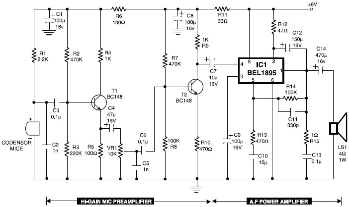
Transistors T1 and T2 form the microphone preamplifier. Resistor R1 provides the necessary bias for the microphone condenser, while preset VR1 functions as a gain control to adjust the gain level. To enhance audio power, the low-level audio output...
R1_47K 1/4W Resistor, R2_4K7 1/4W Resistor, R3_22K 1/4W Resistor, R4_1K 1/4W Resistor, R5, R12, R13_330R 1/4W Resistors, R6_1K5 1/4W Resistor, R7_15K 1/4W Resistor, R8_33K 1/4W Resistor, R9_150K 1/4W Resistor, R10_500R 1/2W Trimmer Cermet, R11_39R 1/4W Resistor, R14, R15_R33 2.5W...
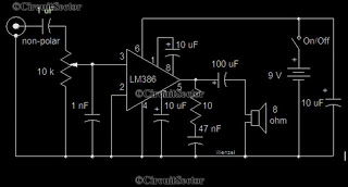
This is a simple low-power audio amplifier circuit capable of producing a power output of 1W. The mono amplifier circuit is built around the LM386 integrated circuit, which operates effectively at low voltages, even below 9V. This low-voltage amplifier...
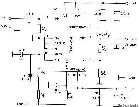
The TDA7294 is a monolithic integrated circuit housed in a Multiwatt15 package, designed to deliver high output power of up to 100W. It is intended for use as an audio Class AB amplifier in high-fidelity applications. The TDA7294 is a...