
Tube Line Preamplifier Project

Building on the basic description, the preamplifier circuit functions as the initial stage of amplification, enhancing the weak input signal from the source into a stronger, more usable form for further amplification or processing. The input selector department plays a crucial role in choosing the desired input signal from multiple sources.
The application voltage delay is a safety feature that ensures the gradual application of voltage to the tube circuits, protecting the components from sudden voltage spikes that could potentially cause damage. The preamplifier output is then connected to the final amplifiers, which boost the signal to a level suitable for driving the speakers or other output devices.
The power supply department is the backbone of the whole circuit, providing the necessary electrical power for the operation of the preamplifier and the final amplifiers. It must be designed to deliver a stable and clean power supply to avoid any noise or distortion in the audio signal.
The SRPP cascade circuit in the next stage is a popular tube amplifier configuration due to its advantages in linearity, gain, and output impedance. It is followed by a cathode repeater circuit at the exit, which helps in maintaining the signal strength and quality before it reaches the final amplifiers.
Overall, this preamplifier circuit, while not revolutionary in design, embodies the essential elements of a reliable and effective tube audio amplification system.The interest for circuits of tubes, remains big. Thus I will give completed in enough big degree, circuit of preamplifier. It is mainly constituted by the department of main preamplifier, the department of input selector, delay of application voltage and connection output of preamplifier with the final amplifiers and the department power supply. The department of mainly preamplifier appears in the Fig.1. Deliberately it does not have something revolutionary in the designing. In the entry exists a simple circuit constituted from relay that is drive from input selector [S2]. The signal afterwards drive to the next stage that is constituted by a circuit cascade S.R.P.P (shunt regulated pushpull) and a circuit cathode repeater, in the exit.
🔗 External reference
Related Circuits
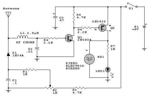
This electronic RF detector project is designed using common transistors and a few standard electronic components. The RF detector responds to RF signals below the standard broadcast band and well over 500 MHz, providing both visual and audible indications...
This Dummy Alarm project causes an LED to flash briefly every 5 seconds, simulating the indicator light of a real alarm. The circuit is designed to consume minimal current to extend battery life, allowing it to remain powered continuously....
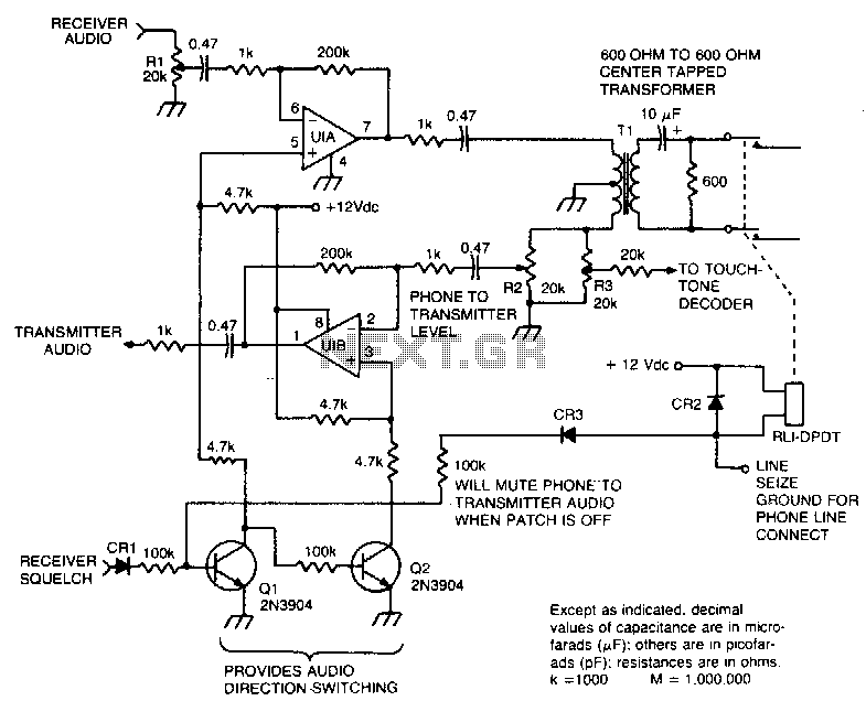
This circuit facilitates the communication link between the receiver and the phone line, as well as the phone line and the transmitter, utilizing an operational amplifier (op-amp) for signal amplification. The described circuit connects a receiver to a phone line...
Power demand in portable designs can require, in specific applications, more than 1 A. A method involves paralleling two DC to DC converters on the same load instead of using a single higher current converter with a lower switching...
This circuit is an FM 88-108 MHz receiver. The FM receiver circuit operates within the frequency range of 88 to 108 MHz, which is the standard FM broadcasting band. The core components of an FM receiver typically include an antenna,...
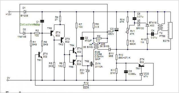
The size of the photoflash charger circuit is significantly simplified and reduced by the Texas Instrument (TI) TPS65552A. This device serves as a photoflash capacitor charger. The TPS65552A is a highly integrated photoflash capacitor charger designed to efficiently charge capacitors...