
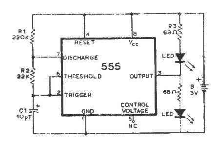
100Hz-1MHz a circuit diagram of the phase meter

The described circuit is intended for precise frequency analysis and is particularly useful in control systems and signal processing applications. It utilizes two sine wave inputs, which are typically generated by function generators or oscillators. The conversion of these sine waves into a square wave is achieved through a comparator or a Schmitt trigger, which ensures that the output transitions cleanly between high and low states.
The overlap of the input sine waves is crucial for determining the characteristics of the resulting square wave. This overlap is defined in relation to the total cycle of the input waveform, impacting the duty cycle of the output signal. The circuit is designed to maintain an accuracy of greater than 2%, which is essential for reliable Bode plot generation, allowing for the analysis of system frequency response.
The mention of a 180-degree phase difference indicates that the sine waves are out of phase, which can be used to create a specific response in the square wave output. This phase manipulation is critical in applications where phase relationships between signals are important, such as in feedback systems or phase-locked loops.
To implement this circuit effectively, careful selection of components is necessary, including operational amplifiers for signal conditioning, resistors for setting gain and offset, and capacitors for filtering. Additionally, the circuit may require calibration to ensure that the output accurately reflects the desired characteristics of the input waveforms. This setup allows for the effective generation of Bode plots, which are instrumental in assessing the stability and performance of various electronic systems. Circuit in the frequency range, an accuracy greater than 2%, for the production of bode curve. Two sine wave into a square wave, while the amount of overlap compared with the t otal input wave cycle. Direct input phase difference between the wave train reaches 180 .
Related Circuits

The circuit depicted in Figure 3-147 utilizes a time relay (KT) adjustable between 1 to 2 seconds to ensure adequate braking time. The relay addresses instances where the actual brake stop time may be insufficient. Additionally, SQ1 and SQ2...

Using a Thomson TEA2025, this stereo amplifier delivers 1 W per channel into a 4-ohm load with a 9-V supply. The input sensitivity is 25 mV peak-to-peak for full output. It is important to ensure that pins 4, 5,...
An integrated circuit is precisely that: an integrated circuit. These small packages combine numerous individual components to perform a specific function. They vary in shape and size depending on their complexity. They are categorized into functions such as audio,...

The circuit diagram of the Swallow CS37-2 type color TV illustrates the feeding tube configuration. The filament voltage is supplied by the line flyback transformer, with a current-limiting resistor R523. The accelerating voltage is managed by D502, which rectifies...

If a page name is not selected by pressing the button, the previously selected page name continues to be used. The value is stored in EEPROM and may be changed at any time. When the unit is first powered...
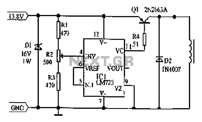
Cars are equipped with a circuit that includes an LM723 regulator, which can serve as a replacement for traditional automobile generator systems that utilize electromechanical charging regulators. This circuit offers superior performance compared to conventional systems. It ensures that...