
100W amplifier circuit

The 100-watt basic power amplifier is structured to ensure high performance while maintaining simplicity in its construction. The input stage, featuring the LF351 op-amp, is essential for providing the necessary open-loop gain. This stage stabilizes the quiescent DC voltage, which is crucial for consistent performance. Following this, the level shift stage ensures that the voltage swing is correctly referenced to the negative rail, allowing for effective signal processing.
The transconductance stage utilizes a Darlington pair, which is advantageous for improving high-frequency linearity. The choice of the 2SC2344 transistor, despite its significant collector-base capacitance, is compensated by the MPSA42, which presents a low impedance and minimizes voltage dependence. The configuration of these transistors, along with the 33 pF pole-splitting capacitor, creates a robust stage that can handle high-frequency signals effectively.
The output stage consists of a full complementary Darlington configuration with paralleled outputs. This design choice enhances the amplifier's capability to drive reactive loads, which can draw substantial current during specific waveform conditions. By using parallel devices, the design increases the damping factor of the amplifier and reduces the maximum current each transistor must handle during peak output conditions. This is particularly important as the gain of power transistors diminishes with increasing current.
Compensation within the amplifier is handled through a two-pole, one-zero configuration. The dominant poles are determined by the op-amp's characteristics and the 33 pF capacitor in conjunction with the 470-ohm bias resistor of the MPSA42. Additionally, a 22 pF feedback capacitor introduces lead compensation, ensuring that the phase lag from the output transistors does not adversely affect high-frequency feedback. This careful design consideration introduces a closed-loop pole that effectively limits high-frequency response, ensuring stability and preventing oscillations.
The amplifier is designed to operate on a +/- 55-volt unregulated power supply, which can be provided by a 40-0-40 volt, 5 amp toroidal transformer and a bridge rectifier, supported by 10,000 µF filter capacitors on each side. Under these conditions, the amplifier can deliver 100 watts continuously into 8-ohm loads without clipping, with dynamic headroom of approximately 1.5 dB. For applications requiring more headroom, the amplifier can accommodate unloaded voltages up to +/- 62 volts without modifications.
While the amplifier is capable of driving 4-ohm speaker systems without current limiting, it is important to note that its short-circuit current limit is set to around 4.5 amps peak. This design allows for handling conventional speaker loads effectively. However, for high-end speakers with low impedance or reactive characteristics, a more powerful amplifier may be necessary to achieve optimal performance. Overall, this 100-watt amplifier offers a balance of performance, simplicity, and cost-effectiveness, making it suitable for various audio applications.This is a 100 watt basic power amp that was designed to be (relatively) easy to build at a reasonable cost. It has better performance (read: musical quality) than the standard STK module amps that are used in practically every mass market stereo receiver manufactured today.
When I originally built this thing, it was because I needed a 100 WPC amp and didn`t want to spend any money. So I designed around parts I had in the shop. The design is pretty much a standard one, and I`m sure there are commercial units out there that are similar. To my knowlwdge, it is not an exact copy of any commercial unit, nor am I aware of any patents on the topology.
To experienced builders: I realize that many improvements and refinements can be made, but the idea was to keep it simple, and should be do-able by anyone who can make a circuit board and has the patience not to do a sloppy job. The input stage is an LF351 op amp which provides most of the open loop gain as well as stabilizes the quiescent dc voltage.
This feeds a level shift stage which references the voltage swing to the (-) rail. The transconductance stage is a darlington, to improve high-frerqency linearity. The 2SC2344 by itself has a rather large collector-base capacitance which is voltage dependent. The MPSA42 presents this with a low-z and has a C(ob) of only a few pf that is effectively swamped by the 33pF pole-splitting cap. The stage is supplied by the 2SA1011 active load (current source) which is about 20 ma. The current to the stage is limited by the 2N3094 to about 70 ma under worst case. The output is a full complementary darlington with paralleled outputs. Although you could "get away with" only one if only 8 ohm easy-to-drive loads are used, this is not recommended.
The use of parallel devices increases the ability to drive reactive loads (which can pull a significant current while the voltage waveform crosses zero and puts a high voltage and a high curent across the transistor simultaneously), gives the amp a higher damping factor, and reduces the maximum current each transistor has to supply to peaks (remember, the gain of a power transistor drops as the current increases). Compensation is two-pole and one zero. The op-amp`s pole and the pole generated by the 33pf cap and the 470 ohm bias resistor of the MPSA42 dominate.
(the 33pF gets multiplied by the stage gain. ) The 22 pf feedback capacitor provides lead compensation, and is taken from the output of the tranconductance stage rather than the output itself. In this way, the phase lag introduced by the output transistors is not seen by the high-frequency feedback.
This intorduces a closed-loop pole which limits the high-frequency response. The two compensation capacitors must be type 1 creamic (NPO) or silver mica - with ZERO voltage coefficient. The amp was designed to run 2 channels off a +/- 55 volt unregulated supply, reducing to +/- 48 volts under full load.
It used a 40-0-40 volt, 5 amp toroid transformer, a bridge rectifier, and 10, 000 uf of filter cap per side. If a standard EI transformer is used, a 6-amp rated unit should be used. With this power supply, it produces 100 watts continuous, both channels driven into 8 ohms resistive with no clipping.
Dynamic headroom is about a db and a half. For more headroom, unloaded voltages to +/- 62 volts can be used with no circuit modification. With no modifications the amp will drive 4-ohm speaker systems with no current limiting. The short-circuit current limit is set to about 4. 5 amps peak, which will handle conventional speaker loads. (It will, of course, produce higher peak currents as the output voltage swing approaches the rail. ) If you are going to be running some of those high-end speakers with impedance minima of half an ohm, or that stay reactive throughout most of the audio band ( ie, 0. 5 +j3. 2 ohms) you will probably already own a better amp than this. If the higher-power Motorola power 🔗 External reference
Related Circuits
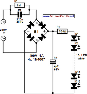
An array of white LEDs can serve as a small lamp for the living room. LED lamps are readily available, resembling standard halogen lamps, and can be installed in a standard 230-V light fixture. A capacitor is employed to...
For several years, a rear fog lamp has been mandatory for trailers and caravans to improve visibility in foggy conditions. When this fog lamp is activated, the fog lamp of the towing vehicle must be turned off to prevent...
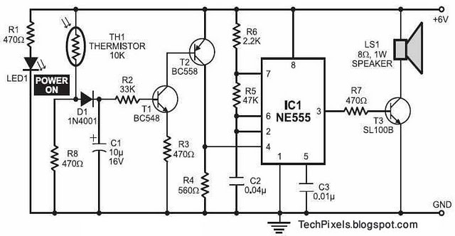
The following circuit illustrates a fire alarm circuit diagram utilizing the NE555 integrated circuit (IC). Features include functioning as a heat sensor and incorporating a 10 kilo-ohm resistor. The fire alarm circuit based on the NE555 IC is designed to...
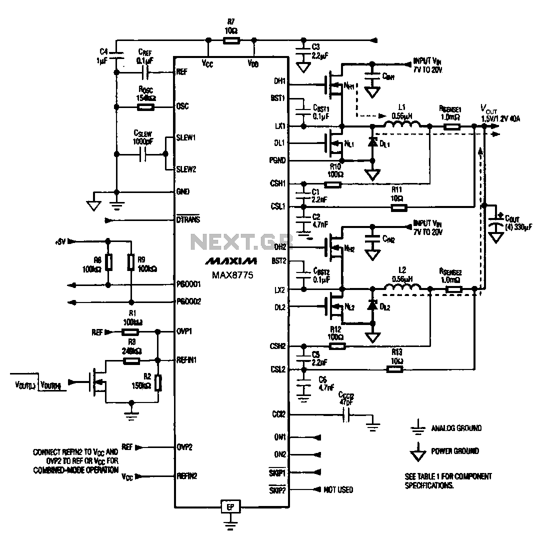
Notebook computer chip power supply circuit, which generates the PWM circuit using MAX8775. The notebook computer chip power supply circuit utilizes the MAX8775 integrated circuit to generate a Pulse Width Modulation (PWM) signal. The MAX8775 is a high-efficiency step-down voltage...
This example describes the use of HS101 and HS201 radio transmitter and receiver modules to control rotating color lights, functioning as a multi-channel radio remote control device suitable for small dance floors or home use. Users positioned at any...
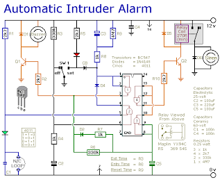
This is a simple single-zone burglar alarm circuit. Its features include automatic exit and entry delays and a timed bell/siren cut-off. It is designed to be used with the usual types of normally-closed input devices such as magnetic reed...