
Fire alarm circuit diagram With NE555 IC

The fire alarm circuit based on the NE555 IC is designed to detect heat and provide an alert in case of fire. The NE555 timer can be configured in various modes, but in this application, it is typically set up in a monostable mode. When the temperature exceeds a predetermined threshold, the heat sensor triggers the NE555, which then activates an output signal.
The circuit includes a heat sensor that responds to temperature changes. This sensor is connected to the trigger input of the NE555 IC. A 10 kilo-ohm resistor is employed in the timing circuit to set the delay duration for the alarm signal. Depending on the specific requirements, additional components such as capacitors may be included to fine-tune the response time and sensitivity of the circuit.
Upon activation, the NE555 can drive a relay or a buzzer to signal an alarm condition. The relay can be used to control higher power devices, such as sirens or notification systems, ensuring that the alarm is effectively communicated.
Power supply considerations are critical; the circuit should be powered by a stable voltage source to ensure reliable operation. Additionally, it is advisable to incorporate protective components, such as diodes, to safeguard against back EMF when using inductive loads.
Overall, this fire alarm circuit provides a robust solution for early fire detection, leveraging the versatility of the NE555 IC in conjunction with a heat sensor and supporting components to ensure timely alerts in emergency situations.The following circuit shows about Fire alarm circuit diagram With NE555 IC. Features: works as the heat sensor, 10 kilo-ohms resistance of the .. 🔗 External reference
Related Circuits
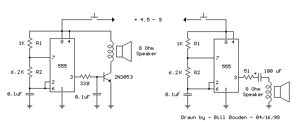
This is a basic 555 square wave oscillator used to produce a 1 kHz tone from an 8-ohm speaker. In the circuit on the left, the speaker is isolated from the oscillator by an NPN medium power transistor, which...
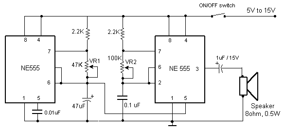
Police siren circuit diagram. This circuit produces a sound similar to a police siren. It utilizes two 555 timer ICs. The police siren circuit typically employs two 555 timer integrated circuits (ICs) configured in astable mode to generate a square...

The music equalizer display schematic is relatively straightforward to construct. It can be assembled on a compact breadboard, utilizing the components listed previously. Due to the high number of connections required, it is advisable to have an ample supply...

The MK484 AM receiver circuit is a simple design based on the MK484 AM receiver IC from Rapid Electronics Ltd. The MK484 is a monolithic integrated circuit that incorporates all necessary sections of an AM receiver, including an RF...

The LEDs operate in an active-low configuration (0), while the initial state of the switches is high (1). In other words, the PC software must send a low signal (0) to activate the LEDs, and if a low signal...
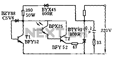
The circuit is designed to activate when the light intensity exceeds 700lx. In this configuration, a phototransistor and the BFY52 transistor are used to trigger the BTY91 thyristor with a current. When light strikes the phototransistor, a positive trigger...