
100W Guitar Amplifier

The amplifier described operates at a rated output of 100W when connected to a 4 Ohm load, which is commonly seen in combo amplifiers utilizing two 8 Ohm speakers wired in parallel. This configuration allows the amplifier to deliver its full power efficiently while maintaining a manageable impedance. An alternative configuration involves connecting the amplifier to a quad box, which consists of four 8 Ohm speakers arranged in a series-parallel configuration. In this setup, the total load impedance is effectively reduced to 4 Ohms, allowing the amplifier to output approximately 60 Watts. For enhanced sound pressure levels, utilizing two quad boxes in conjunction with the amplifier head will enable the system to reach the full 100W output, significantly increasing the volume compared to the dual speaker setup.
The preamp circuit, as illustrated in Figure 1, exhibits unique characteristics that distinguish it from conventional designs. The simplicity of the design belies its sophistication, as it is engineered to provide a broad tonal range suitable for various musical styles. The gain structure within the preamp is optimized to allow for a versatile response, accommodating both clean and distorted signals without sacrificing audio fidelity. The thoughtful arrangement of components within the circuit ensures minimal noise and distortion, contributing to the overall performance of the amplifier. This preamp design offers musicians the ability to shape their sound effectively, making it a valuable feature in the amplifier's architecture.The amp is rated at 100W into a 4 Ohms load, as this is typical of a "combo" type amp with two 8 Ohm speakers in parallel. Alternatively, you can run the amp into a "quad" box (4 x 8 Ohm speakers in series parallel - see Figure 5 in Project 27b, the original article) and will get about 60 Watts.
For the really adventurous, 2 quad boxes and the amp head will provide 100W, but will be much louder than the twin. The preamp circuit is shown in Figure 1, and has a few interesting characteristics that separate it from the "normal" - assuming that there is such a thing. This is simple but elegant design, that provides excellent tonal range. The gain structu 🔗 External reference
Related Circuits
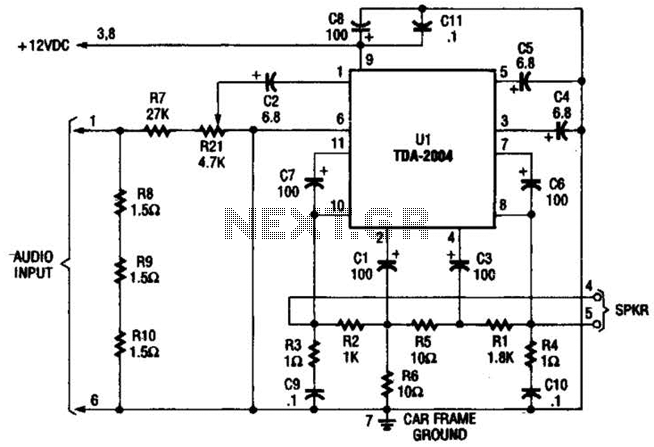
Only one channel of this circuit is shown. The other is practically identical. The input to the circuit, taken from the speaker output of a car radio, is divided into two paths. In one path, a high-power divider network...
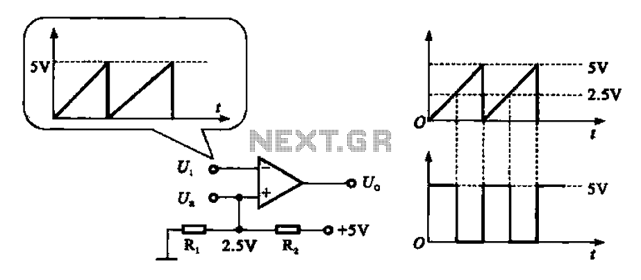
The addition and subtraction functions of an operational amplifier are facilitated through an external feedback network, which places the integrated operational amplifier in a deep state of negative feedback. In this linear region, the relationship between input and output...
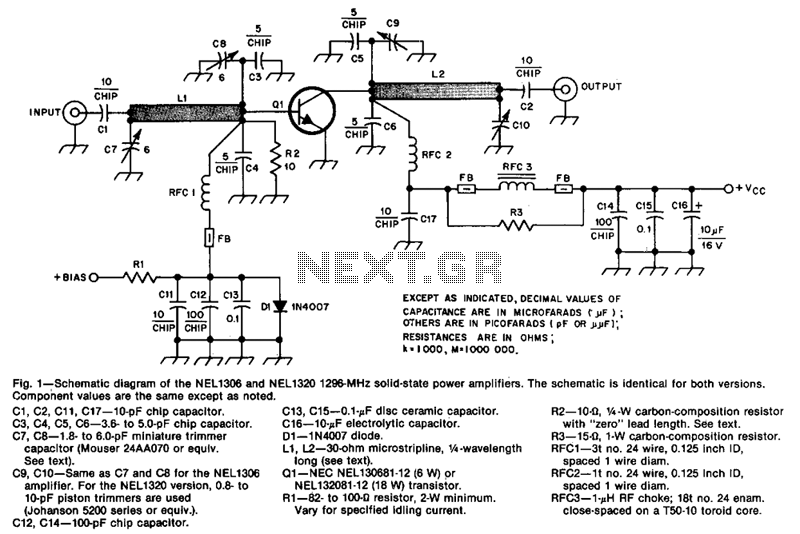
The design incorporates 30-ohm, 1/4 microstrip lines on the input and output. Capacitors C3, C4, C7, and C8, along with inductor L1, form a pi network that matches the low input impedance of the device to 50 ohms. Capacitors...
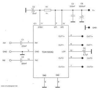
This is a 22-watt car stereo audio amplifier. The circuit is based on a single IC TDA1553 with a few peripheral components. This IC is designed for car audio applications. The TDA1553CQ integrates two 22-watt amplifiers with differential input...
In addition to its primary function as a headphone amplifier, this circuit is applicable in various scenarios requiring a wide bandwidth low power amplifier. It utilizes an operational amplifier (op-amp) with its output current enhanced by a pair of...
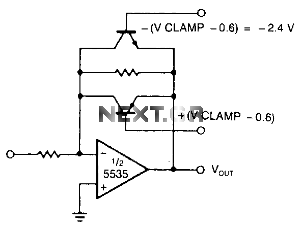
The modified inverting amplifier employs an active clamp to precisely limit the output swing. Consideration must be given to the VBE of the transistors. The output swing is restricted by the base-emitter breakdown of the transistors. A straightforward circuit...