
Stereo Headphone Amplifier Circuit Schematic

This circuit is designed to provide amplification across a broad frequency range while maintaining low power consumption, making it suitable for portable and battery-operated devices. The operational amplifier serves as the core component, responsible for signal processing and initial amplification. The inclusion of transistors at the output stage is crucial, as it allows for increased current drive capability, enabling the circuit to drive low-impedance loads such as headphones or speakers effectively.
The configuration typically involves a feedback loop connected to the op-amp, which stabilizes the gain and improves linearity. The choice of transistors is essential; they should be selected based on their current handling capacity and frequency response to ensure optimal performance. The circuit may also include passive components such as resistors and capacitors to set the gain, filter unwanted frequencies, and stabilize the power supply.
For applications beyond headphone amplification, this circuit can be adapted for use in audio processing equipment, signal conditioning for sensors, or as part of a larger system requiring low power amplification. The versatility of the design allows for modifications to accommodate various input and output requirements, making it a valuable addition to any electronic engineer's toolkit.Apart from the obvious usage as a headphone amplifier, the circuit can be used for a range of applications where a wide bandwidth low power amplifier is needed. The circuit is based on an opamp, with its output current boosted by a pair of transistors 🔗 External reference
Related Circuits
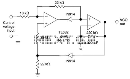
This circuit utilizes the AD639 universal trigonometric function generator from Analog Devices to transform a triangle waveform, which serves as the fundamental waveform of the VCO, into a low-distortion sine wave. By operating the AD639 in its frequency tripler...
If you want to test an amplifier, a dummy load may be more convenient for speakers to use than actual speakers, due to noise or damage to the speakers. This circuit behaves in terms of impedance and frequency response...
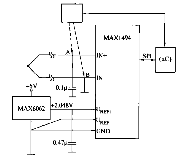
The circuit consists of the MAX1494 and a thermocouple temperature measurement system. The MAX1494 is terminated at 1N GND 5-32. An external temperature sensor, such as the DS75, can be utilized for junction temperature compensation. The MAX1494 employs an...
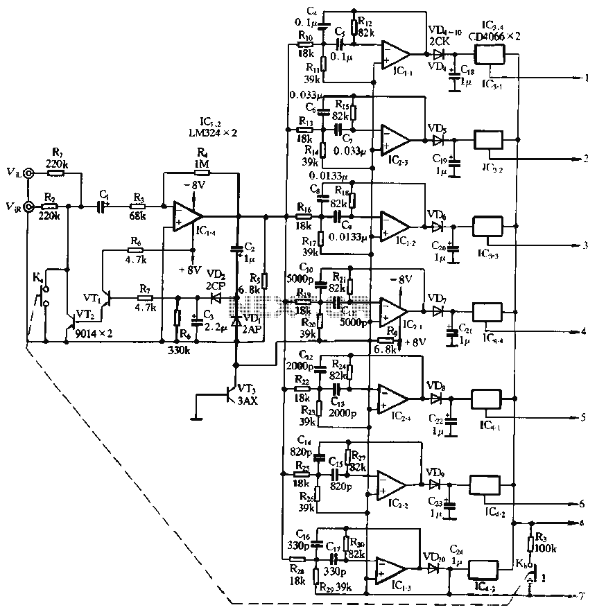
The structure and working principle of this circuit are fundamentally similar to the previous circuit, with some variations in the components used. The circuit is divided into seven bands, with center frequencies selected at 60 Hz, 150 Hz, 400...
Any PIC microcontroller equipped with an ADC and sufficient memory to accommodate the program can be utilized. An LED is pulsed after each ADC acquisition to indicate the processor's activity, allowing for verification of software functionality. The LCD voltmeter...
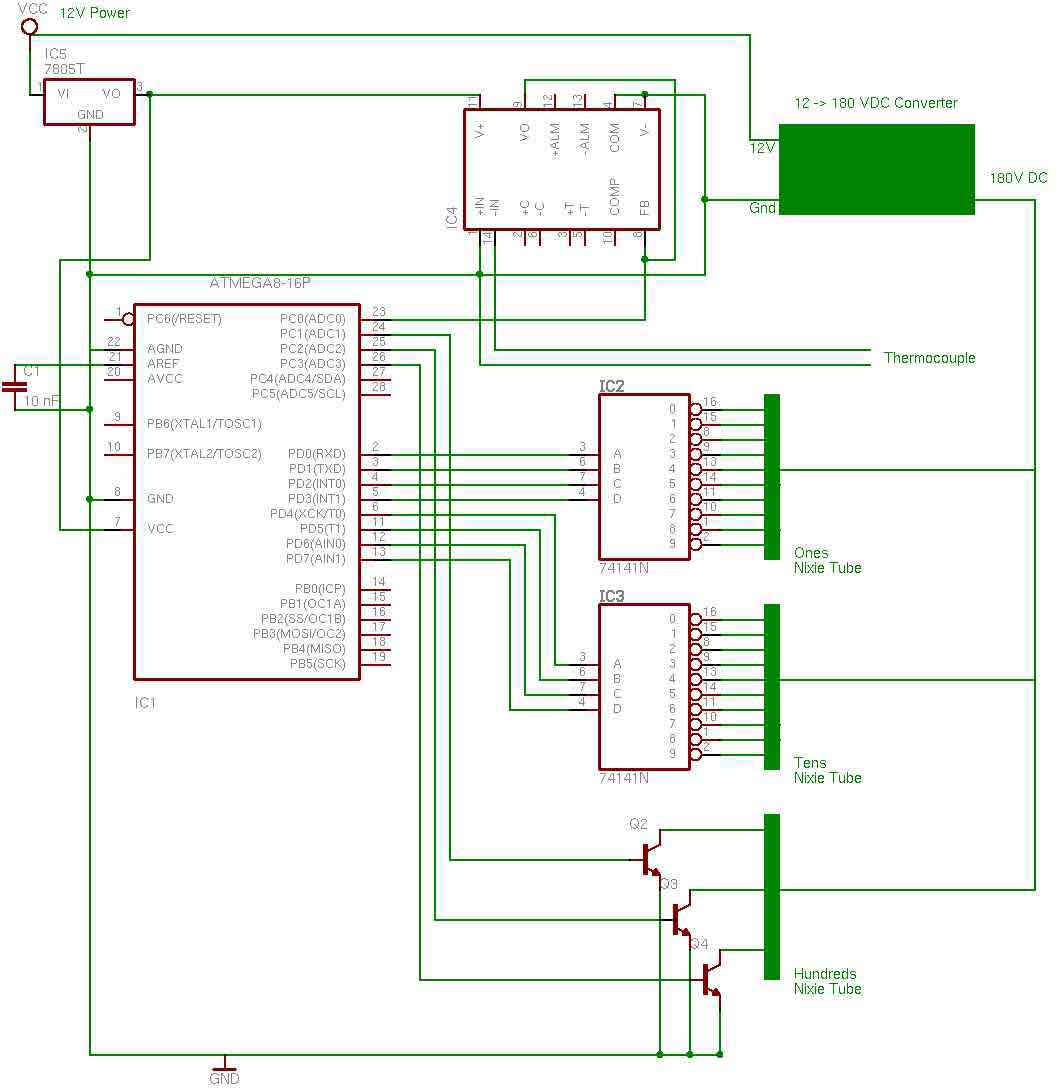
the entire circuit is comprised of integrated circuits. This makes for some easy organization when it goes to the circuit board for soldering. In addition, I used only 3 of the pins on the 3rd nixie tube for the...