
100W MOSFET power amplifier circuit using IRFP240 IRFP9240

The Hi-fi 100W MOSFET power amplifier circuit is designed to provide high-quality audio amplification with minimal distortion. It operates from a dual power supply of 45V, which is essential for achieving the required output power levels. The circuit is capable of delivering 100W to an 8-ohm speaker and 160W to a 4-ohm speaker, making it suitable for a variety of audio applications.
The use of MOSFETs (Metal-Oxide-Semiconductor Field-Effect Transistors) in the output stage of the amplifier contributes to its ability to handle higher power levels while maintaining low distortion. MOSFETs are known for their high input impedance and linear characteristics, which help in reproducing audio signals accurately.
In terms of circuit design, the amplifier typically includes a differential input stage to enhance common-mode rejection and improve overall sound quality. Feedback mechanisms are implemented to stabilize the gain and reduce distortion. Capacitors and resistors are strategically placed throughout the circuit to filter noise and stabilize the power supply.
Thermal management is also a critical aspect of this amplifier design. Heatsinks are often employed to dissipate heat generated by the MOSFETs during operation, ensuring reliable performance over extended periods. Additionally, protection circuits may be included to prevent damage to the amplifier or connected speakers in the event of overload conditions.
Overall, the Hi-fi 100W MOSFET power amplifier circuit is engineered for audiophiles seeking high fidelity sound reproduction, combining power, efficiency, and low distortion for an enhanced listening experience.Hi-fi 100W mosfet power amplifier circuit . Operates from 45v dual supply. 100W to 8 ohm speaker, 160W to 4 ohm speaker, low distortion.. 🔗 External reference
Related Circuits
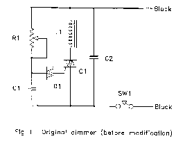
The circuit (before flameout) worked like this: device Q1 is a triac, which is a power-switching device. When triggered, it switches to a fully conducting state and stays that way until the current passing through it goes to zero....

Channel 7 presents a circuit diagram of a smart temperature sensor using the MAX6698. This circuit includes three transistors (VT1, VT2, and VT3) and three thermistors (RT1, RT2, and RT3). An internal reference voltage source is provided via resistors...
5 Volt/1.5A Switching Power Supply based on the TNY264P power supply. Refer to the designated page for an explanation of the related circuit diagram. The 5 Volt, 1.5A switching power supply utilizing the TNY264P is a compact and efficient power...

The circuit diagram was designed to create a power supply without utilizing any transformer circuit. This circuit illustrates the advantages as well as the limitations of transformerless power supplies. The transformerless power supply circuit typically employs a capacitive dropper method...
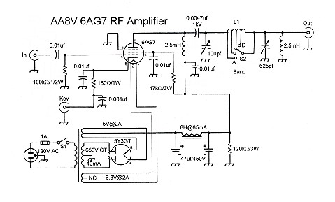
The input coupling capacitor allows the input signal to pass through to the grid of the tube while preventing the input source from potentially shorting the grid bias to ground. If the grid bias were shorted out, the 6AG7...

The circuit depicted in the figure comprises a PGA103 programmable gain instrumentation amplifier. This design utilizes the PGA205 and PGA103 in a cascading configuration, resulting in a total gain for the amplifier. The gain is determined by the product...