
With a 7-Channel Smart Temperature Sensor MAX6698 circuit diagram

The circuit configuration of the MAX6698 smart temperature sensor is designed to monitor temperature variations accurately through the use of thermistors, which are temperature-sensitive resistors. The three thermistors (RT1, RT2, RT3) are strategically placed to measure different temperature points, allowing for a comprehensive assessment of environmental conditions. Each thermistor's resistance changes with temperature, producing a corresponding voltage drop that is read by the MAX6698.
The transistors (VT1, VT2, VT3) serve as amplifiers or switches in the circuit, enhancing the signal received from the thermistors. The choice of transistors, such as CMPT3904, SST3904, KST3904-TF, SMBT3904, and FMMT3904CT-ND, provides flexibility in terms of performance characteristics, including gain and frequency response, which can be critical depending on the specific application.
The internal reference voltage source, created by the resistors UREF REX1, REX2, and REX3, ensures that the thermistors are powered adequately and consistently. This stable power supply is crucial for accurate temperature readings, as fluctuations in voltage can lead to erroneous measurements.
Overall, the MAX6698 circuit diagram illustrates a sophisticated approach to temperature sensing, integrating multiple components to achieve precise and reliable performance in various applications, from industrial monitoring to consumer electronics. The design's modular nature allows for easy adjustments and scalability, making it suitable for a wide range of temperature sensing needs. Channel 7 has a circuit diagram of a smart temperature sensor MAX6698 is shown in Figure: MAX6698 maximum temperature with three transistors (VT1 ~ VT3) and three thermistors ( RT1 ~ RT3). The internal reference voltage source via a resistor UREF REX1 ~ REX3 were given three thermistor power supply, the voltage drop across the thermistor respectively supplied THER1 ~ THER3 pins. Temperature transistor can be used CMPT3904, SST3904, KST3904-TF, SMBT3904, FMMT3904CT-ND models.
Related Circuits
This is a silicon transistor circuit showing typical voltage values. When the forward base/emitter voltage is 0.6 to 0.7 V, the transistor is silicon. Germanium transistors will have a forward base/emitter bias voltage of 0.2 to 0.3 V. This...

The relay power in the linear circuit is derived from a -120 V bias supply, while the transmit keying output from the Kenwood device is +12 V with a maximum current of 10 mA. A critical component of this...
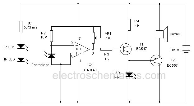
This infrared alarm barrier is designed to detect individuals passing through doorways, corridors, and small gates. The transmitter emits an infrared light beam that is not visible to the human eye. When the beam is interrupted by a person,...
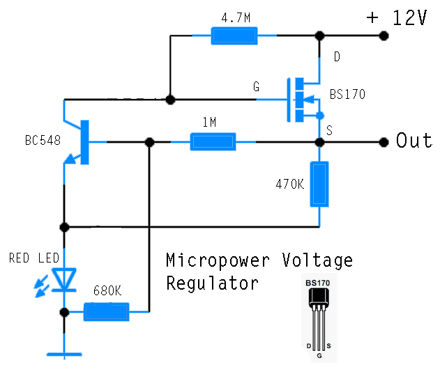
This circuit is designed to power an AVR microcontroller from a 12V lead-acid battery. The watchdog component consumes only 14 µA. While integrated circuits (ICs) from manufacturers like Linear Technology or Maxim can be utilized for this purpose, they...

This document presents a collection of engaging and challenging electronic circuits that can be built for enjoyment. The author has a long-standing passion for electronics, having studied the subject since middle school and developed numerous circuits over the years....
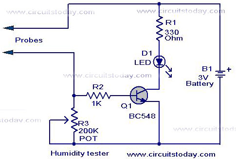
A simple humidity tester circuit using only an LED, a transistor, and a few resistors is explained with a clear circuit schematic. The humidity tester circuit is designed to provide a visual indication of humidity levels using basic electronic components....