
100W RF Amplifier Circuit With BLY94 Transistor

The 100W RF amplifier circuit utilizing the BLY94 transistor is designed to amplify radio frequency signals efficiently. The BLY94 is a high-performance RF power transistor known for its capability to handle high frequencies and provide substantial output power. In this configuration, it is essential to ensure proper biasing and load matching to maximize efficiency and minimize distortion.
The circuit typically includes an input stage that may consist of a matching network to couple the RF signal into the base of the BLY94. This matching network often employs inductors and capacitors to achieve the desired impedance transformation. The inductor plays a crucial role in tuning the circuit to resonate at the desired frequency, which enhances the amplifier's performance.
The output stage of the amplifier is designed to deliver the amplified RF signal to the load, which could be an antenna or another stage of amplification. It is vital to include appropriate filtering components to suppress unwanted harmonics and ensure that the output signal remains clean and within the specified frequency range.
Thermal management is another critical aspect of the design, as the BLY94 can generate significant heat during operation. Adequate heat sinking and possibly active cooling solutions should be incorporated to prevent thermal runaway and ensure reliable operation.
Overall, the design of the 100W RF amplifier with the BLY94 transistor requires careful consideration of component selection, circuit layout, and thermal management to achieve optimal performance in RF applications.This is a part of a 100W RF amplifier. This circuit built based on RF power transistor BLY94. Component: BLY94 Transistor, Inductor, .. 🔗 External reference
Related Circuits
This circuit is designed to indicate, via a flashing LED, when room noise exceeds a predetermined threshold, selectable from three fixed levels: 50 dB, 70 dB, and 85 dB. The circuit utilizes two operational amplifiers to amplify the sound...
Create an H-Bridge for controlling a DC brushed motor using PWM. One bridge will control one DC motor. The bridge will have three inputs: A, B, and PWM. Inputs A and B will determine the direction of the motor,...
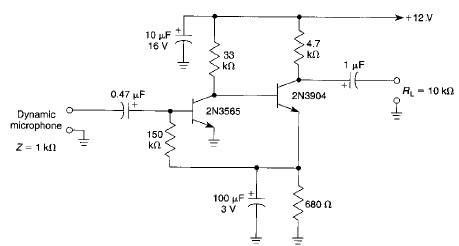
This microphone preamplifier electronic project is based on transistors and is capable of approximately 70 dB or more gain at audio frequencies. The gain of this circuit is roughly equal to the product of the hfe (current gain) of...
This FET audio mixer exemplifies the versatility of Field Effect Transistors (FETs). Although FETs were originally designed for high-frequency applications, they are also highly effective in audio frequency applications. The circuit can accommodate an unlimited number of inputs, provided...
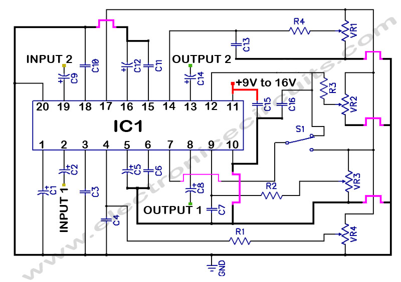
LM1036 Stereo Tone (Bass, Treble, Volume, Loudness, Balance) Controller Circuit. The LM1036 is a DC controlled tone (bass/treble), volume, and loudness controller designed for audio applications. The LM1036 circuit serves as an integrated solution for controlling various aspects of audio...
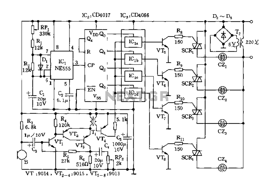
The circuit includes a controller that integrates an acoustic-electric conversion and amplification circuit, a clock pulse generator, a counting circuit, and a control circuit. It manages four accompanying music tracks and flashing lights. Microphones (MIC) convert sound into electrical...