
555 Music lantern controller circuit diagram

The circuit operates by first capturing sound through microphones, which convert acoustic signals into electrical signals for processing. The 555 timer is configured in astable mode, generating a continuous square wave output that serves as a clock signal for the CD4017 counter. The timing components are selected to allow for a flexible oscillation period, which can be adjusted to suit the desired timing of the light and sound synchronization.
The CD4017 counter is a decade counter that counts the clock pulses and activates its outputs sequentially. Each output corresponds to a specific timing interval, allowing for a precise control of the lighting sequence. The connection of the reset terminal allows for the counter to be reset after reaching the maximum count, ensuring that the sequence can repeat indefinitely.
The analog switches (CD4066) are utilized to route the strobe signals to the respective outputs, effectively controlling the activation of the SCRs. These SCRs are used to switch the power to the lights, enabling them to flash in sync with the music. The overall design ensures that the audio and visual elements are harmoniously integrated, providing an engaging experience through synchronized music and lighting effects. The careful selection of components and their configuration allows for a versatile and dynamic performance, suitable for various applications such as entertainment systems, stage performances, or interactive installations.Controller as shown, including the acoustic-electric conversion and amplification circuit, a clock pulse generator, counting circuit and control circuit. It controls four accom panying music and lights flashing light. Microphones MIC song will sound into electrical signals, VT1 ~ VT4 was added to quad analog switch IC3 (CD4066). 555 and RP1, R1, R2, D1, C1 and other components astable multivibrator t charge 0.693 (RP1 + R1) C1 t put 0.693R2C1 T 0.693 (RP1 + R1 + R2) C1 Oscillation period T illustrated parameters vary within the range of 0.5 to 5 seconds.
3-pin output 555 added to the IC2 as a CP pulse. IC2 using CMOS type decimal counter/pulse distributor CD4017, under the clock CP action, Q0 (3 feet), Q1 (2 feet), Q2 (4 feet) Q3 (7 feet), Q4 (10 feet) high power have emerged level pulse, and Q4 was added to a reset terminal R (15 feet), the circuit becomes a ring counter circuit. Output Q0 ~ Q3 will in turn four analog switches CD4066 strobe signal sequentially added to the Song VT5, VT6, VT7, VT8, and sequentially turned on, SCR1 ~ SCR4 turn trigger conduction, followed by a power socket lights, lanterns order lights, with melodious music, lights flashing brilliance.
Related Circuits
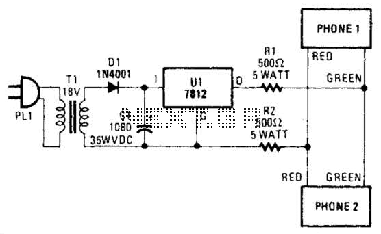
Two telephones can be used as an intercom by utilizing this circuit. Older style rotary phones that are non-electronic may be the most suitable for this application. Additionally, handsets alone can be powered in this manner. This intercom circuit allows...
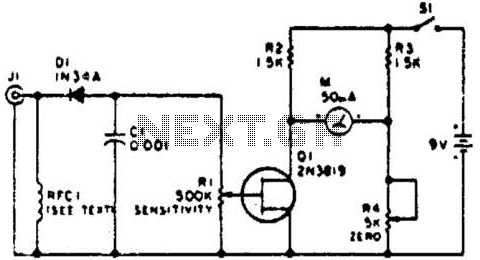
This circuit employs a FET as a DC amplifier within a bridge configuration. Resistor R4 is adjusted for meter nulling with switch J1 short-circuited. Any surplus 50-mA meter can be utilized in this circuit. RFC1 represents a suitable RF...
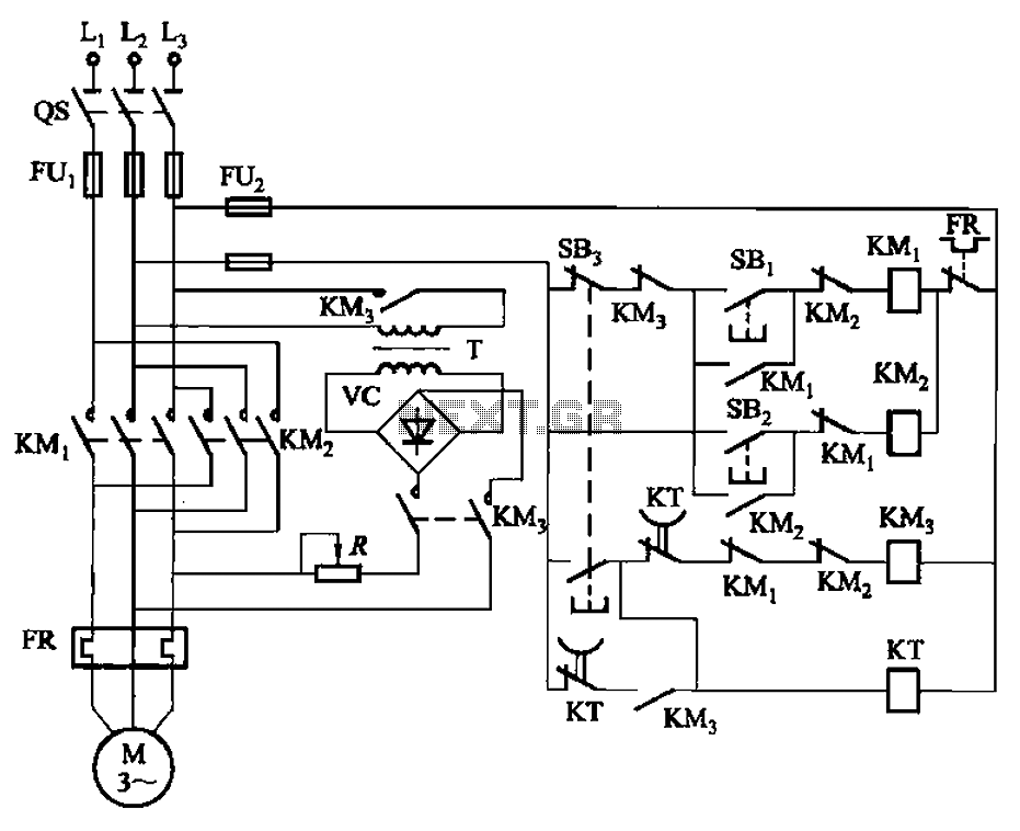
The circuit illustrated in Figure 3-144 depicts an automatic control system for dynamic braking. It utilizes a time relay (KT) to manage the operational duration, along with a step-down transformer (T) and a single-phase bridge rectifier. The circuit includes...
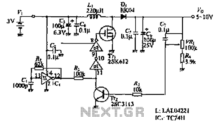
The design of the power supply circuit diagram utilizes an oscillator circuit from the 74HC series of CMOS logic circuits, with a MOSFET as the switching device. This configuration allows for the development of small-scale power supplies suitable for...
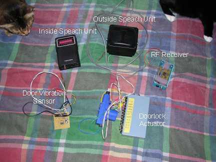
Our present car controller runs on a single PIC16F870 micro and provides functions for remote door locks, headlight reminder, and car finder. It is constructed using wire-wrap to allow for future expansion and is mounted using Velcro on the...
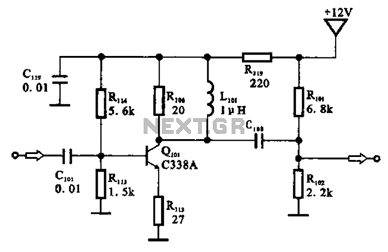
The amplifier circuit is designed as a pre-amplifier configuration. It utilizes transistor Q101 and other components such as inductor L101 and biasing elements. The transistor operates as a common emitter intermediate frequency (IF) amplifier. The IF signal is coupled...