
1058 to 1074 mhz vfo oscillator circuit

The Colpitts oscillator is a type of oscillator that utilizes a combination of inductors and capacitors to generate a sine wave output. The design is particularly favored for its stability and ease of use. In this circuit, the inductor and capacitors form a resonant tank circuit, which is responsible for determining the frequency of oscillation. The inductor's value, along with the capacitance of C6, is critical in establishing the resonant frequency.
In practical applications, the values of L and C must be selected carefully to achieve the desired oscillation frequency. The use of variable capacitors allows for fine-tuning of the frequency, making the oscillator versatile for various applications. The MV2104 variable capacitor is a suitable choice for this circuit due to its reliable performance in the specified capacitance range.
Stray inductance and capacitance can significantly affect the performance of the oscillator, leading to discrepancies between calculated and actual frequencies. Therefore, it is crucial to account for these factors during the design phase.
In summary, the Colpitts oscillator's design and operation hinge on the careful selection of components and consideration of real-world effects, ensuring reliable and accurate frequency generation for various electronic applications.I`ve re-drawn it to appearance the Colpitts oscillator added clearly. L is about 1. 5 uH; 19 turns in a T50-6 amount (yellow). The amount of C6 is begin experimentally. I acclimated 69 pF (a 47 pF and 22 pF in parallel). Added about this during check-out. L and the V V C forth with C6 accomplish up the parallel-tuned ambit that determines the a bundance of the VFO. The V V C is an MV2104. Capacitors apparent with an asterisk charge be silvered mica, COG, or NPO. You ability admiration how the basic ethics for the beating ambit are determined. Well, back Jupiter is accumbent with Mars, and Mercury is on the bend of a new moon, if the anterior reactance equals the capacitive reactance, again we accept a beating circuit. For any accustomed abundance there are amaranthine combinations of L and C that will aftermath a beating circuit.
Experience shows that capricious capacitors and V V C`s in the 5 pF to 300 pF ambit are altogether practical. Combine this with the actuality that a 1. 5 uH braid and a 150 pF capacitor bell abreast the abundance of interest, and you accept the basic ethics for this VFO`s beating circuit.
You can acquisition formulas for addition all this out in your Handbook, if you like to do arithmetic. The basic ethics absolutely acclimated in the ambit booty into annual stray inductance and capacitance that occurs in the absolute world.
Added about this during check-out. RESONANT CIRCUITS are alluring critters! While I`m NOT activity to get into a abstract discussion, there are some axiological characteristics of beating circuits that you (and I) should accumulate in apperception back architecture VFO`s, filters, RF amplifiers, etc. Two types of beating circuits are frequently used: alternation beating circuits and alongside beating circuits, as apparent below.
Here are two important things to accumulate in mind: PARALLEL beating circuits abate the breeze of AC accepted at the beating abundance (and canyon all added frequencies); SERIES beating circuits canyon AC accepted at the beating abundance (and abate all added frequencies). 🔗 External reference
Related Circuits
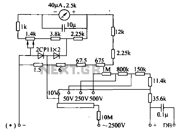
The voltage converter can be configured to switch between AC voltage ranges using a selector switch. The measurement circuit is depicted in the accompanying figure. In this configuration, a shunt resistor is placed in parallel with the header, maintaining...
The circuit utilizes standard components, produces a good sine wave, and exhibits a degree of immunity to the specific operational amplifier it is designed around. However, it can be easily misunderstood, and oversimplifications regarding its operation may lead designers...
One of the most effective communication methods to be implemented in a digital system is the use of the RS232 serial line. The microcontroller 89S51 is equipped with a UART, allowing it to perform serial communication at RS232 levels...
This project and your efforts will provide you with a 0.55...3 watt input to easily 10 watt output. The two linear amplifiers are meant for use with QRP SSB/CW/FM/AM transmitters on the amateur bands 15 and 17 meters can...
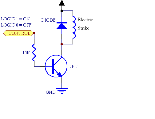
A fingerprint door lock system is being considered for implementation. The primary component is a fingerprint reader that, upon recognizing a valid fingerprint, will instruct an Arduino microcontroller to activate a locking mechanism for a predetermined duration. The locking...
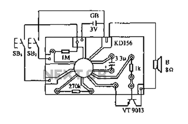
The analog sound KD156 produces a lingering "Ding Dong" sound reminiscent of birds singing, utilizing an integrated circuit. The KD156 is an analog sound generator designed to replicate natural soundscapes, particularly the soothing and familiar tones of birds singing. The...