
Electric strike with Arduino circuitry

The described fingerprint door lock system integrates several key components to create a secure and efficient access control mechanism. The fingerprint reader serves as the primary input device, capturing and processing biometric data to authenticate users. This reader is connected to an Arduino microcontroller, which acts as the central processing unit. Upon successful fingerprint verification, the Arduino sends a signal to the locking mechanism, activating it for a specified duration to allow entry.
The locking mechanism, an electric door strike, is designed to be compatible with standard door hardware and is powered by a 12-volt DC power supply, which provides sufficient current (2000mA) to ensure reliable operation. The selected power supply must be capable of delivering consistent voltage and current to both the fingerprint reader and the locking mechanism without fluctuations that could affect performance.
The term "12V Return" likely refers to the return path for the electrical current after it has passed through the locking mechanism. This return path is essential for completing the circuit and ensuring that the locking mechanism operates correctly. It is crucial to connect this return line appropriately to the power supply to avoid potential issues with the system's functionality.
In the event that an electromagnet is considered as an alternative to the electric strike, it is important to ensure that the electromagnet's specifications align with the power supply and control logic of the Arduino. The electromagnet would require a similar voltage and current rating to function effectively. Additionally, the control circuit may need to be modified to accommodate the characteristics of the electromagnet, such as incorporating a relay or transistor to handle the inductive load.
Overall, this fingerprint door lock system has the potential to provide enhanced security and convenience. Careful attention to component compatibility, circuit design, and power management will be essential for successful implementation.A fingerprint door lock, and the only thing that`s stopping me from purchasing the components is knowing if my setup is going to work or not. Is this an acceptable setup For the actual fingerprint reader, I was going to use this one, , which upon receiving the correct fingerprint, tell the Arduino to send power to the lock to unlock it for a certain amount of seconds.
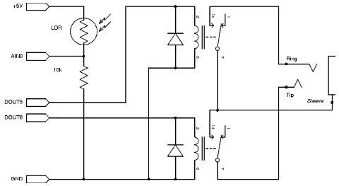
The strike that I will be using is similar to the " Electric Door Strike for Schlage Locks, " and the power supply will be similar to the " Linear Corporation AAE00381 12-Volt DC 2000ma Power Supply. " Do these schematics make sense After discussing this with HikeOnPast below, I believe I copied his schematics correctly.
I`m not sure what he meant by "12V Return" from the strike but I assumed it is the same as sending it back to the power. Would the above work with an electromagnet substituted for the strike (I`m assuming yes, I would just need to find parts that are compatible with the magnet)
🔗 External reference
Related Circuits
A straightforward project involves using an Arduino to rotate a GH-2 camera on a fluid head by specified degrees to capture 360-degree panoramas. The motor control is uncomplicated, and there is a wealth of DIY motor projects available. Assistance...

The circuit includes an optical input circuit (VD, 3DU12), a pulse forming circuit (IC1A, IC1B functioning as a voltage comparator; optical coupler; transistor switching circuit), and a counting and display circuit. The circuit architecture consists of several key components that...
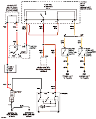
This circuit below shows an electrical circuit applicable for the Audi A4 Quattro 2004 model year. Component: Transmission, Anti-lock Brakes Circuit. The electrical circuit for the Audi A4 Quattro 2004 model year encompasses critical components such as the transmission system...

Synchronous switching activates only when the AC supply voltage crosses zero and deactivates only when the current reaches zero. This circuit responds to either a mechanical switch or a variable resistance, such as a cadmium-sulfide photocell. It minimizes disturbances...
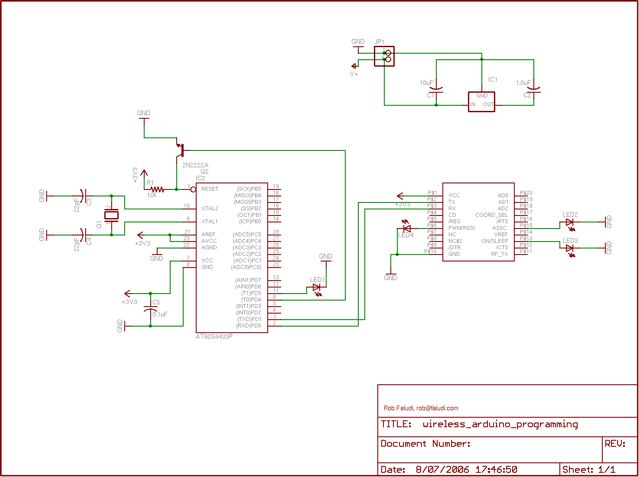
The Arduino system provides a straightforward and open-source approach for programming microcontrollers. Typically, this involves using a serial or USB cable directly connected to the microcontroller project. However, challenges arise when the project is located in inaccessible areas, such...
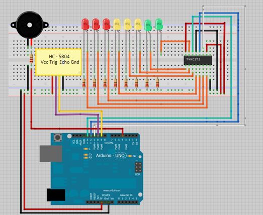
This is a tutorial for beginners who have recently started learning about electronics. The author has prior experience in programming with C and Python. The schematic presented in this tutorial is designed for novice electronics enthusiasts who are transitioning from...