
10Mhz coaxial line driver

The HA2530 integrated circuit is designed to handle high-frequency applications, making it suitable for driving lines that require significant power and current. The circuit's performance is characterized by its ability to maintain a flat frequency response, which is crucial for applications where signal integrity is paramount. The equation f(−3 dB) = Vz p RfCf indicates that the bandwidth is determined by the product of the feedback resistor (Rf) and the feedback capacitor (Cf), along with the voltage reference (Vz).
To implement this circuit effectively, careful selection of Rf and Cf is necessary to achieve the desired bandwidth while ensuring stability. The feedback loop is critical for maintaining the linearity of the output signal, and the absence of peaking indicates that the circuit can operate effectively across its intended frequency range without introducing unwanted harmonic distortion.
In practical applications, the HA2530 can be utilized in various high-frequency communication systems, audio amplifiers, and other electronic devices where high output current and low distortion are required. The design should also consider thermal management, as high output levels can lead to increased heat generation. Proper layout techniques, including minimizing trace lengths and ensuring adequate grounding, will further enhance the performance of the circuit.
Overall, this circuit design provides an efficient solution for high-frequency line driving needs, ensuring reliable operation with high fidelity in signal transmission.The circuit will find excellent usage in high frequency line driving systems that require wide-power bandwidths at high output current levels. (IC=HA2530) The bandwidth of the circuit is limited only by the single pole response of the feedback components;namely f(—3 dB) = Vz p RfCf
As such, the response is flat with no peaking and yields minimum distortion.
Related Circuits
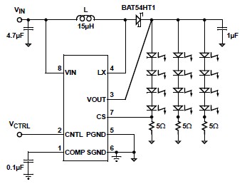
A simple white LED driver schematic can be created using the EL7513 constant current boost regulator, which is specifically designed for driving white LEDs. This driver can manage 4 LEDs in series or up to 12 LEDs in a...
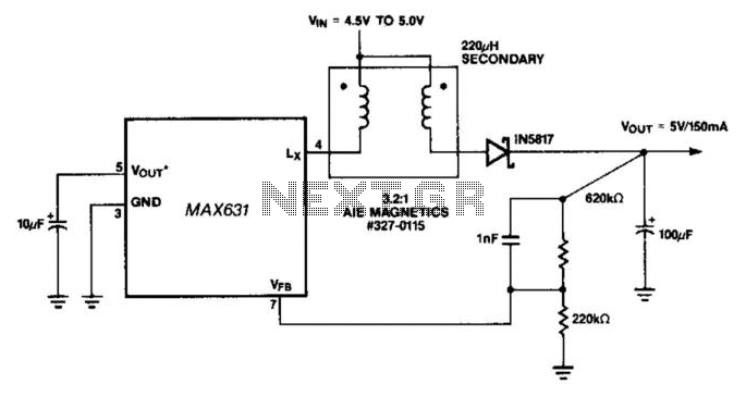
This circuit offers a distinctive solution to a prevalent power distribution issue at the system level. When the supply voltage to a remote board must travel through a lengthy cable, the voltage at the termination point may decrease to...
The circuit is a MOSFET based linear voltage regulator with a voltage drop of as low as 60 mV at 1 ampere. Drop of a fewer millivolts is possible with better MOSFETs having lower RDS(on) resistance. The circuit uses...
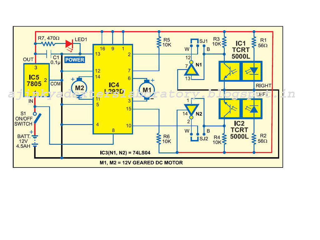
Carefully examine the following circuit diagram and attempt to construct the circuit on a breadboard first. If it functions correctly, proceed to create its PCB version. The circuit diagram serves as a blueprint for constructing an electronic circuit on a...
The SP1481E, SP1485E, SP1490E, and SP1491E series transceivers, combined with the SP6652 high-efficiency, high-frequency current mode PWM buck regulator, facilitate the creation of an isolated RS-485 interface capable of providing up to 2kVrms isolation. This configuration supports CAN communication...
An extremely simple and low cost Sine/Square wave generator based on the Analog Devices AD9835 Direct Digital Synthesis (DDS) Generator chip. The frequency can be set for any frequency from 1Hz to 10MHz in 1Hz resolution steps! All this...