
10Mhz Frequency Counter Circuit

The crystal frequency is further divided to generate a short store pulse at pin 2 of U2, followed by a short reset pulse at pin 14 of U2 after approximately 0.4 ms. The frequency of the pulses is dictated by the state of U2 pin 11. When pin 11 of U2 is grounded through S1, the pulses occur every 2 seconds, causing U2 pin 2 to go high for one second, which prevents additional input signals from entering U1. This action transfers the count latched in U1's internal counters to the display. Subsequently, U2 pin 13 goes low for one second, allowing a new count to be entered into the seven-decade counters of U1. This cycle repeats, continuously updating the display every two seconds. When U2 pin 11 is connected to the positive supply rail (+5 V), the store and reset pulses occur at 0.2-second intervals, resulting in a 0.1-second count period. Ten input pulses must be counted for a '1' to appear on the first digit, D1, indicating that the frequency being measured is ten times larger than the frequency displayed. In this mode, the decimal points are activated to visually signify that the 0.1-second count period is in use. The display requires at least seven common-cathode multiplexed LED digits, and any common-cathode seven-segment display can be employed; no specific display is mandated.
The electronic circuit operates efficiently by utilizing the ICM7208 and ICM7207A integrated circuits to manage counting and timing functions. The ICM7208 (U1) serves as the primary counter, capable of counting up to ten digits, which is essential for applications requiring high precision in frequency measurement. The multiplexing capability allows for the display of multiple digits without the need for numerous individual connections, thus simplifying the design.
The oscillator controller (U2) is crucial for generating the timing signals necessary for the operation of the counter. The division of the crystal frequency into lower frequencies for multiplexing and pulse generation ensures that the display updates at regular intervals, providing an accurate representation of the measured frequency. The use of a CA3130 biFET op-amp (U3) allows for the conditioning of the input signal, ensuring that it meets the required specifications for counting by U1.
The design also incorporates a flexible input mechanism through S1, enabling the user to toggle between different counting modes, thereby adjusting the frequency measurement period as needed. This adaptability is particularly useful in various measurement scenarios where different time bases might be required.
Overall, the circuit is designed to provide a reliable, user-friendly frequency measurement tool with a clear digital output, making it suitable for a range of applications in electronics and instrumentation. The choice of components and the architecture of the circuit ensure that it remains versatile and efficient for the intended purpose. The circuit consists of an ICM7208 seven-decade counter (Ul), an ICM7207A oscillator controller (U2), and a CA3130 biFET op amp (U3). Integrated circuit Ul counts input signals, decodes them to 7-segment format, and outputs signals that are used to drive a 7-digit display.
Integrated circuit U2 provides the timing for Ul, wliile U3 conditions the input signal to provide a suitable waveform for input to Ul. The 5.24288-MHz crystal frequency is divided by U2 to produce a 1280-Hz multiplexing signal at pin 12 of U2.
That signal is input to Ul at pin 16 and is used to scan the display digits in sequence. The cathodes of each digit are taken to ground several times each second, activating any segments of the digits whose anodes are high as the result of decoding by Ul. The crystal frequency is further divided to produce a short store pulse at pin 2 of U2, followed (after about 0.4 ms) by a short reset pulse at pin 14 of U2. The frequency of the pulses is determined by the state of U2 pin 11. When pin 11 of U2 is taken to ground through SI, the pulses occur every 2 seconds and cause U2 pin to go high for one second, which prevents additional input signals from entering Ul.
That causes the count latched in Ul`s internal counters to be transferred to the display. Integrated circuit U2 pin 13 then goes low for one second, allowing a new count to be entered into the seven decade counters of Ul. That cycle is repeated, continuously updating the display every two seconds. When U2 pin 11 is taken to the positive supply rail (+5 V), the store and reset pulses occur at 0.2-s intervals, resulting in a 0.1-s count-period.
Ten input pulses must be counted in order for a 1 to appear on the first digit, Dl, so that the frequency being measured is obviously 10 times larger than the frequency that is shown on the display. In that mode, the decimal points are driven by and visually indicate that the 0.1-s count period is being used.
The display must have at least seven 7-segment common-cathode multiplexed LED digits. Any common-cathode seven-segment display can be used; no particular display is specified.
Related Circuits
The following circuit illustrates the Weller WLC100 Electronic Soldering Station Circuit Diagram. This circuit utilizes the Q4012LPH Transistor. Features include safety measures, temperature control, and functionality as a soldering station that performs effectively for various applications. It is a...
This unit would be mounted in a small plastic or preferably metal box, with a 9V battery, level control, a male XLR connector (same as on a mic) and a switch. Current drain is low, since the circuit only...
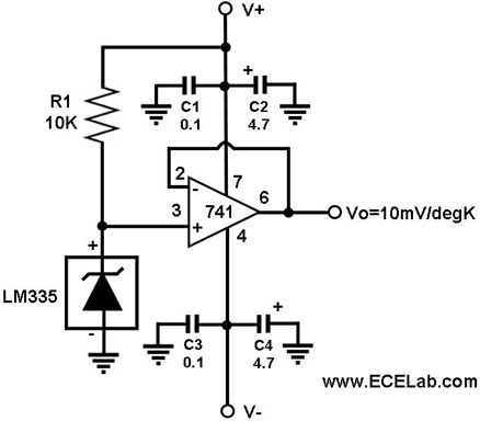
In this circuit, the LM335 is utilized as a temperature sensor, an integrated circuit that converts ambient temperature into an equivalent output voltage. The LM335 is a precision temperature sensor that provides a linear output voltage proportional to the absolute...
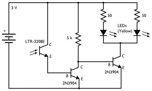
Here is an inexpensive electronic circuit that can be built to place in a Jack-o'-lantern. It provides power to drive a few LEDs at night and automatically turns them off during the daytime. This is a simple and automatic...
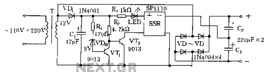
The circuit is automatically converted to a low-voltage configuration. A 220V AC supply is stepped down by transformer T. After this, the breakdown voltage of diode VDw causes transistors VT1 and VT2 to turn off, resulting in the solid-state...
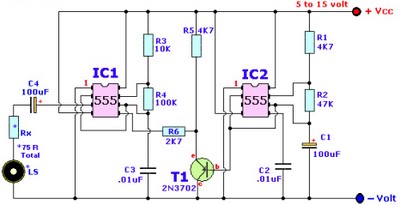
Browse home alarm circuit explanation latest schematic siren wailing with latest Wailing Alarm Siren circuit schematic with explanation. The loudspeaker LS and the resistor marked Rx should be together 75 ohms. If a standard 8-ohm speaker is used, then...