
latest Wailing Alarm Siren circuit Schematic with explanation
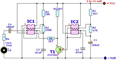
The Wailing Alarm Siren circuit is designed to produce a loud, attention-grabbing sound, typically used in security systems or alert mechanisms. At the heart of this circuit is a loudspeaker (LS) which requires an appropriate resistor (Rx) to ensure optimal performance and sound quality. The combination of the loudspeaker and the resistor should total 75 ohms to achieve the desired output.
For an 8-ohm loudspeaker, the calculated resistor value is 67 ohms. However, in practice, the nearest standard resistor value of 68 ohms is recommended. This small adjustment helps to maintain the integrity of the sound produced while ensuring the circuit operates safely without overloading the components. Similarly, for a 4-ohm loudspeaker, a resistor value of 71 ohms is suggested, while for a 25-ohm loudspeaker, a resistor value of 50 ohms is appropriate.
The circuit may include additional components such as transistors, diodes, or capacitors to enhance functionality, control the sound output, or manage power distribution. Each component plays a critical role in the overall performance of the siren, ensuring that it can produce a loud, wailing sound that effectively alerts individuals in the vicinity. Proper selection of these components is essential for achieving the desired performance characteristics of the alarm system.Browse » home » alarm » circuit » explanation » latest » schematic » siren » wailing » with » latest Wailing Alarm Siren circuit Schematic with explanation *The Loudspeaker LS and the resistor marked Rx should be together 75 ohms. If you have a standard 8-ohm speaker then Rx is 67 ohms. The nearest value is 68 ohms. So for a 8 ohm lou dspeaker Rx is 68 ohms. For a 4 ohm loudspeaker Rx is 71 ohms, for a 25 ohm loudspeaker Rx is 50 ohms, etc, etc. 🔗 External reference
Related Circuits
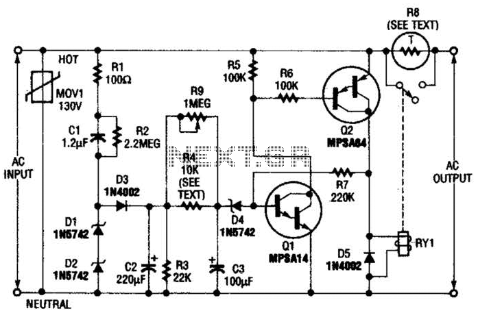
Q1 is an NPN Darlington transistor, and Q2 is a PNP Darlington transistor. MOV1 is a metal-oxide varistor, while R8 is a thermistor used for limiting inrush current. This circuit is designed to limit AC line current to a...
Originally, the tank cost around Php 400 but was later sold for approximately a hundred pesos less. Recognizing a great deal, the decision was made to purchase the toy. Opening the toy proved to be somewhat challenging. The track...
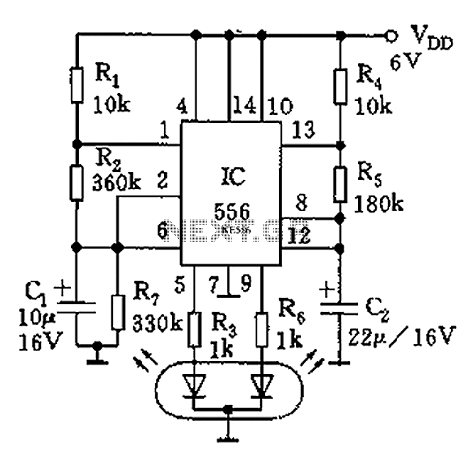
The circuit features a dual-core 556 timer IC and a light-emitting diode (LED) tube. The left half of the IC (556 1/2) comprises resistors R1, R2, capacitor C1, etc., generating a frequency of approximately 2 Hz in a multivibrator...
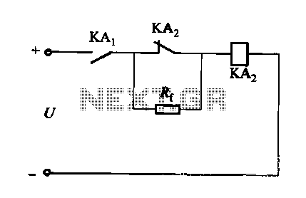
A DC relay or contactor is utilized to enhance the excitation pull-in and release mechanisms in a circuit. The relay circuit, as depicted in Figure 6-28, facilitates improved return line efficiency. When the control relay KAi is activated, its...
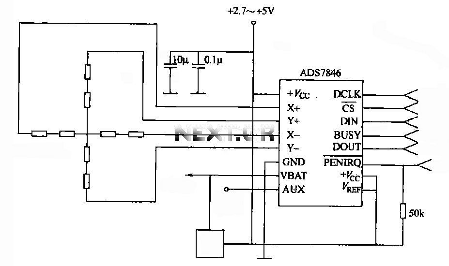
A 4-wire resistive touch screen utilizes an ADS7846 interface circuit. The ADS7846 analog chip incorporates electronic switches and a successive approximation A/D converter. The analog switch chip controls the switching of the X+ (or Y+) positive supply terminal, while...
With this tester you can check whether a diode is working properly. In the table you can see what LED to indicate the positions of the switch and condition of the diode. The circuit can be connected to a...
Warning: include(partials/cookie-banner.php): Failed to open stream: Permission denied in /var/www/html/nextgr/view-circuit.php on line 713
Warning: include(): Failed opening 'partials/cookie-banner.php' for inclusion (include_path='.:/usr/share/php') in /var/www/html/nextgr/view-circuit.php on line 713