
10W Audio Amplifier with Bass-boost

This audio amplifier circuit is designed to provide a reliable and effective solution for driving small loudspeaker systems while addressing common frequency response issues associated with such applications. The NE5532 Dual IC is selected for its favorable performance characteristics, including low noise and distortion, making it suitable for high-fidelity audio amplification.
The circuit configuration allows for a maximum output power of approximately 11.5W, which is adequate for small to medium-sized loudspeakers. The incorporation of a bass-boost control is particularly advantageous, as it allows users to enhance low-frequency performance without introducing significant quality degradation. The specified bass lift of +16.4dB at 50Hz ensures that the amplifier can deliver a satisfying low-end response, which is often a critical requirement in audio applications.
In terms of frequency response, the gentle rise in output at lower frequencies, even with the bass control set to its lowest position, indicates that the amplifier maintains a balanced sound profile. The specified frequency response adjustments (+0.8dB at 400Hz, +4.7dB at 100Hz, and +6dB at 50Hz) suggest that the design has been optimized to ensure clarity and presence across the audio spectrum, particularly in the bass region.
Grounding is a critical aspect of this design. To prevent hum and ground loops, all ground connections should be made at a single point. This practice minimizes potential interference and ensures a clean audio signal. Specifically, the ground connections for the input jack (J1), potentiometer (P1), and capacitors (C2, C3, and C4) should converge at a common point, while the output capacitor (C9) should also connect to this ground point.
Overall, this audio amplifier design balances power output, frequency response, and ease of implementation, making it an excellent choice for users seeking a reliable audio amplification solution without the need for hard-to-find components.This design is based on the 18 Watt Audio Amplifier, and was developed mainly to satisfy the requests of correspondents unable to locate the TLE2141C chip. It uses the widespread NE5532 Dual IC but, obviously, its power output will be comprised in the 9. 5 - 11. 5W range, as the supply rails cannot exceed ±18V. As amplifiers of this kind are freque ntly used to drive small loudspeaker cabinets, the bass frequency range is rather sacrificed. Therefore a bass-boost control was inserted in the feedback loop of the amplifier, in order to overcome this problem without quality losses. The bass lift curve can reach a maximum of +16. 4dB @ 50Hz. In any case, even when the bass control is rotated fully counterclockwise, the amplifier frequency response shows a gentle raising curve: +0.
8dB @ 400Hz, +4. 7dB @ 100Hz and +6dB @ 50Hz (referred to 1KHz). * A correct grounding is very important to eliminate hum and ground loops. Connect in the same point the ground sides of J1, P1, C2, C3 &C4. Connect C9 at the output ground. 🔗 External reference
Related Circuits
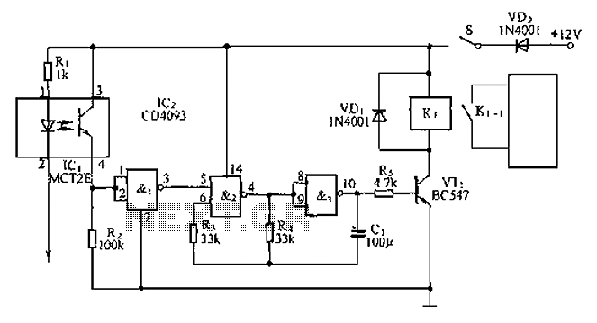
An anti-theft car audio system circuit is depicted, powered by a 12V DC supply from the car battery. Upon closing switch S1, the light-emitting diode in optocoupler IC1 activates, causing the phototransistor to conduct. This results in a high-level...
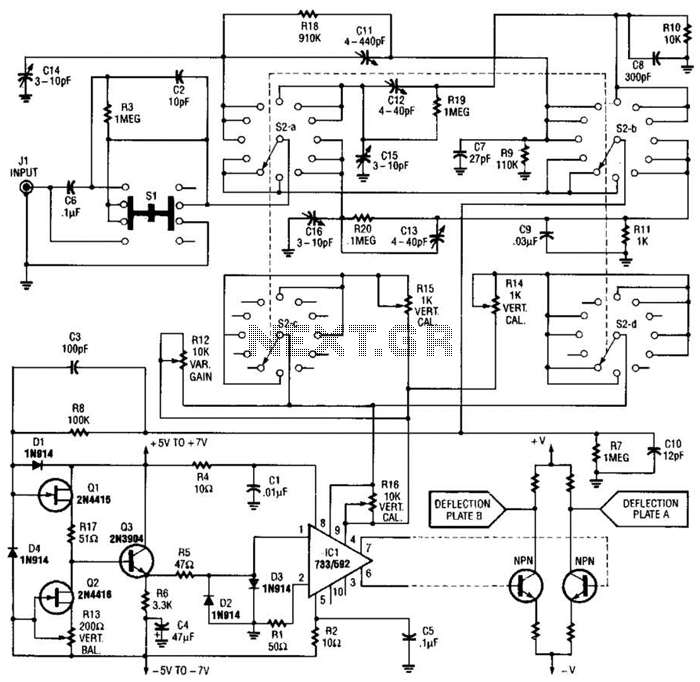
An oscilloscope front-end amplifier can be constructed using low-cost transistors and video amplifier integrated circuits (ICs). This preamplifier utilizes a FET input along with compensated attenuators, achieving an approximate bandwidth of 100 MHz, which is sufficient for most general-purpose...
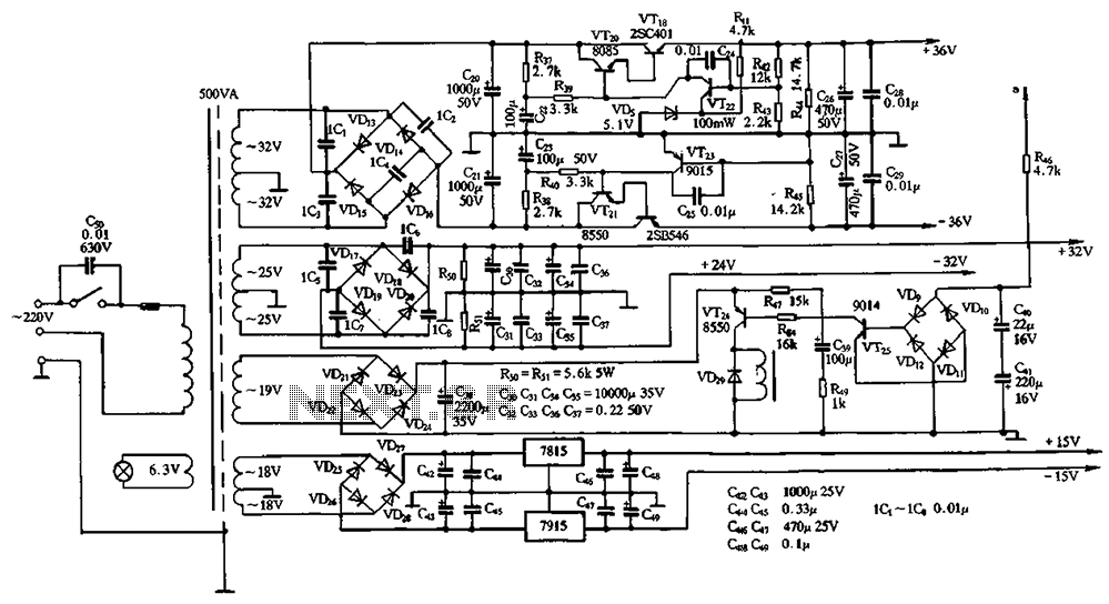
The power supply circuits for servo systems are critical during both the adoption and operational stages. The power supply circuit for servo systems is designed to provide stable and adequate voltage and current levels necessary for the servo motors to...
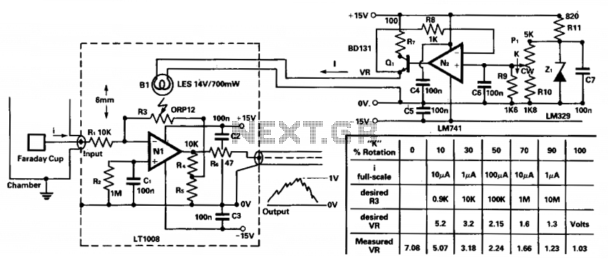
To amplify small current signals, such as those from an electron collector inside a vacuum chamber, it is beneficial for reasons related to noise and bandwidth to utilize a "head amplifier" connected to the chamber. The operational amplifier N1...
This amplifier circuit integrates the LT1010 with a fast discrete stage and employs an LT1008-based DC stabilization loop. It features a differential stage that operates in a single-ended configuration. The described amplifier circuit is designed to enhance signal amplification while...
The circuit is designed to establish a monitoring and surveillance system for a remote location, functioning as a room monitor or baby alarm. The proposed circuit for the monitoring and surveillance system incorporates various electronic components to ensure reliable operation...