
Oscilloscope Preamplifier Circuit

The design of an oscilloscope front-end amplifier is critical for ensuring accurate signal representation and measurement. The use of low-cost transistors and video amplifier ICs allows for a cost-effective solution without compromising performance. The FET (Field Effect Transistor) input stage is particularly advantageous due to its high input impedance, which minimizes loading effects on the signal source. This characteristic is essential for preserving the integrity of the input signal, especially in applications involving high-frequency signals.
Compensated attenuators are integrated into the design to manage the signal levels effectively, allowing for a dynamic range that can accommodate various input signal amplitudes. This feature is vital for general-purpose oscilloscopes, which often need to analyze signals with differing voltage levels without distortion.
The amplifier's bandwidth of approximately 100 MHz is a critical specification, as it determines the frequency range over which the amplifier can accurately process signals. This bandwidth is adequate for most general-purpose applications, enabling the oscilloscope to capture and display fast-changing waveforms, such as digital signals or high-frequency analog signals.
In summary, the combination of a FET input, compensated attenuators, and a bandwidth of 100 MHz makes this front-end amplifier design suitable for a wide range of oscilloscope applications, ensuring reliable performance in signal measurement and analysis. An oscilloscope front-rend amplifier can be built with low-cost transistor and video amp ICs. This preamp uses a FET input and compensated attenuators, and has approximately 100-MHz bandwidth, which is adequate for most general-purpose oscilloscopes.
Related Circuits
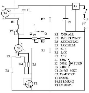
There are many digital thermometers with ±1°C displays, but their accuracy is approximately ±1°C and they cannot be calibrated. A thermometer circuit was created using components available at a local electronics hobby shop, providing an educational experience. For a...
This circuit is mainly intended to provide common home stereo amplifiers with a microphone input. Using a stereo microphone the circuit must be doubled. In this case, two separate level controls are better than a dual-ganged stereo potentiometer. Low...
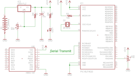
There are two schematics to examine for constructing a transmitter/receiver system. The first schematic is the transmitter, featuring a variable trimpot connected to RA0. The trimpot's value will be transmitted from the Tx pin of the PIC to the...
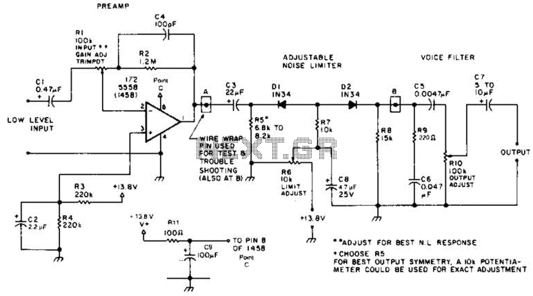
A preamplifier in the audio frequency range amplifies a noisy audio signal to drive a diode clipper. Suitable audio input levels would be in the 10-mV to 1-V range. The audio preamplifier circuit is designed to enhance weak audio signals, typically...

Electronic FM Telephone Transmitter Schematic. The following schematic design illustrates a circuit diagram for an FM telephone transmitter built on a compact PC board layout. This small design allows it to be easily integrated within the housing of a...
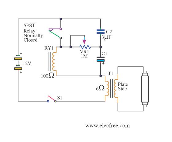
This is a flashing blink circuit designed for 12V applications. It utilizes a small-sized fluorescent lamp and operates through a relay that modifies the circuit from DC to AC. The flashing blink circuit operates at a voltage of 12V, making...