
10W Audio Amplifier With Bass-Boost
The 18 Watt audio amplifier design employs the NE5532 dual IC, which is well-regarded for its low noise and high performance in audio applications. This amplifier circuit is configured to deliver a power output that is constrained by the ±18V supply rails, ensuring that the output remains within the specified range of 9.5 to 11.5 watts. The incorporation of a bass-boost control within the feedback loop is a strategic enhancement that allows for improved low-frequency response, which is often lacking in amplifiers driving small loudspeakers. This control facilitates a maximum bass lift of +16.4 dB at 50 Hz, providing users with the ability to tailor the audio output to their preferences.
The frequency response characteristics of this amplifier are noteworthy, as they reveal a gradual increase in output even when the bass control is minimized. The amplifier demonstrates a +0.8 dB increase at 400 Hz, a +4.7 dB increase at 100 Hz, and a +6 dB increase at 50 Hz when referenced to a standard 1 kHz signal. These attributes contribute to a well-rounded audio experience, making the amplifier suitable for various applications, including home audio systems and small public address systems.
Furthermore, the design emphasizes the importance of proper grounding to mitigate potential issues such as hum and ground loops, which can adversely affect audio quality. It is recommended that all ground connections—specifically those for J1, P1, C2, C3, and C4—be consolidated at a single point to ensure a common ground reference. Additionally, connecting capacitor C9 to the output ground helps maintain signal integrity and reduces the likelihood of interference.
Overall, this amplifier design combines practical components and thoughtful engineering to deliver an effective solution for audio amplification needs, particularly in scenarios where space and component availability may be limited.This design is based on the 18 Watt Audio Amplifier, and was developed mainly to satisfy the requests of correspondents unable to locate the TLE2141C chip. It uses the widespread NE5532 Dual IC but, obviously, its power output will be comprised in the 9. 5 - 11. 5W range, as the supply rails cannot exceed ±18V. As amplifiers of this kind are freque ntly used to drive small loudspeaker cabinets, the bass frequency range is rather sacrificed. Therefore a bass-boost control was inserted in the feedback loop of the amplifier, in order to overcome this problem without quality losses. The bass lift curve can reach a maximum of +16. 4dB @ 50Hz. In any case, even when the bass control is rotated fully counterclockwise, the amplifier frequency response shows a gentle raising curve: +0.
8dB @ 400Hz, +4. 7dB @ 100Hz and +6dB @ 50Hz (referred to 1KHz). A correct grounding is very important to eliminate hum and ground loops. Connect to the same point the ground sides of J1, P1, C2, C3 &C4. Connect C9 to the output ground. 🔗 External reference
Related Circuits
Often, a small amplifier is required to accommodate the needs of compact spaces. This amplifier can be configured as either mono or stereo, and its circuitry is capable of efficiently driving two small speakers. Constructing the amplifier necessitates only...
For SR AB763 driver replace: 25k pot, 0.1uF cap and 4k7 resistor with 100 ohm resistor to ground. 56k resistor with 820 to 4k7 resistor. More: 6k8 resistor with 22k resistor. The circuit modification described involves specific component replacements and...
There is no substitute for sheer power—low-efficiency speakers, outdoor sound systems, or perhaps the full dynamic range of a high-power amplifier. Whatever the requirement, this super power module should meet the needs. The amplifier can be divided into three...
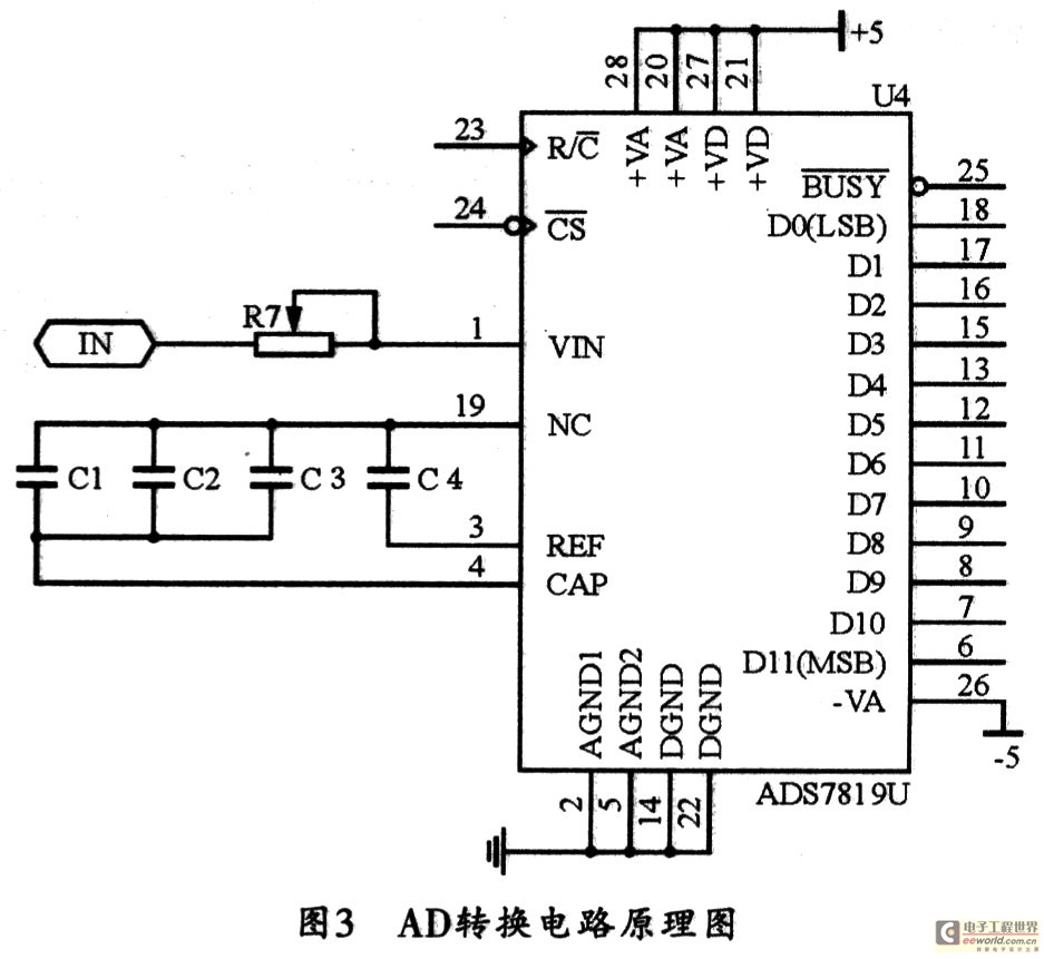
With the rapid advancement of microelectronics and technology in information systems, digital technology represented by microcontrollers is evolving continuously. Microcontrollers are characterized by their small size, low power consumption, high expandability, and convenience in control functions. They are widely...
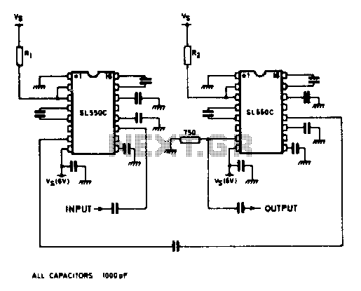
A wideband high gain configuration using two SL550s connected in series. The first stage is connected in a common emitter configuration, while the second stage is a common base circuit. Stable gains of up to 65 dB can be...
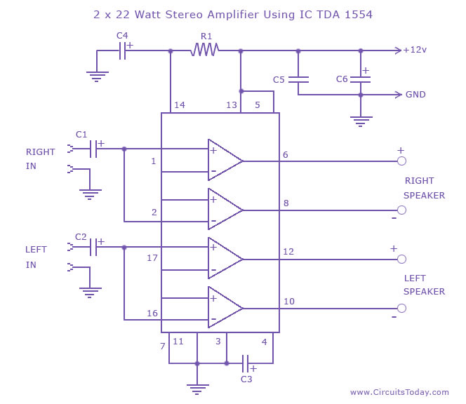
A high-quality stereo amplifier circuit of 44 Watts (22 Watts per channel) using the TDA 1554 IC. This is a powerful audio amplifier circuit for 2 channels. The described stereo amplifier circuit utilizes the TDA 1554 integrated circuit (IC), which...