
8W Amplifier with TDA2003 circuit
The amplifier's design for each channel is based on the TDA2003 integrated circuit by SGS THOMSON, which features five terminals. Internally, it comprises a complete audio amplifier circuit. The design requires minimal external components to drive loudspeakers effectively. This integrated circuit is capable of handling very low impedance loads, down to 1.6Ω. The output power increases as the load impedance decreases, although the relationship between output power and load is non-linear. The output power is influenced by the supply voltage and the load resistance; thus, increasing the supply voltage will enhance the power output.
The total harmonic distortion (THD) for the TDA2003 is low, typically around 0.2%, although it can reach up to 10% under certain conditions. Distortion tends to rise sharply as the amplifier approaches maximum output power, and is influenced by both the output power level and the frequency of the input signal.
The output terminal of the integrated circuit can deliver high peak currents of up to 3.5A, while exhibiting very low crossover distortion. A notable feature of this amplifier is its durability under challenging conditions; however, caution is advised against short-circuiting any terminal to prevent damage.
The frequency response of the amplifier spans from 40Hz to 15kHz (-3dB) at an output power of 1W with a 4Ω load. The input impedance is 150kΩ at 1kHz, with a quiescent current consumption of 45mA, which increases with output intensity.
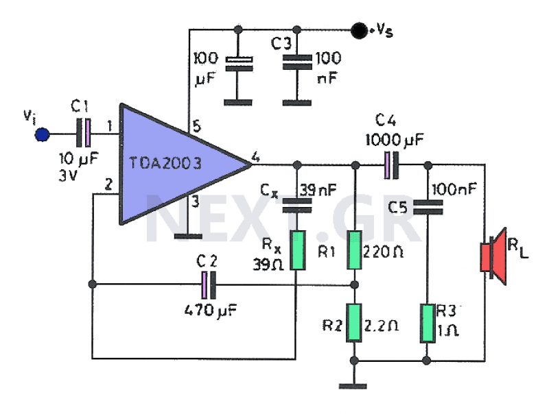
The theoretical circuit diagram of the amplifier illustrates its design based on the TDA2003, which functions as a standalone amplifier. By utilizing two integrated circuits, a stereo amplifier configuration can be achieved to meet various audio needs. The amplifier delivers a minimum output power of less than 1W with a supply voltage of 8V. For stereo applications, two complete circuits are required, with four for quadraphonic sound.
The circuit layout includes posts for two integrated circuits, designed for stereo use. The assembly of components for both left and right channels employs identical materials. The circuit is powered by a simple supply line, where both positive and negative lines share a common terminal. For added safety, a fuse can be placed in line with the positive supply.
The entire assembly can be mounted on a metal chassis, with the integrated circuits requiring heat sinks for effective thermal management. A 12V transformer is used to power the amplifier, with the voltage rectified through a bridge and filtered using a 4700μF electrolytic capacitor. The amplifier can also be powered by a car's electrical system or a regulated power supply with an output voltage of up to 18V. The construction process is relatively straightforward, provided that attention is paid to the polarity of the electrolytic capacitors and the proper orientation of the integrated circuits.
Assembly should begin with the resistors and electrolytic capacitors, followed by the insertion of the integrated circuits. Testing the amplifier does not necessitate the installation of heat sinks, provided that the power draw is minimal and the testing duration is brief.
Components:
| Resistors | Capacitors | Other |
|-------------------|----------------------|----------------------------|
| R1 = 220Ω | C1 = 2.2μF | IC1 = TDA2003 |
| R2 = 2.2Ω | C2 = 470μF | IC2 = TDA2003 |
| R3 = 1Ω | C3 = 0.1μF | SP1 = speaker 4Ω/30W |
| Rx = 39Ω | C4 = 1000μF/25V | |
| | C5 = 100nF | |
| | Cx = 39nF | |Many times a small amplifier is needed to meet the needs of small spaces. This amplifier can be either mono or stereo, with this circuitry you can comfortably drive two small speakers. To build the amplifier you do not need anything but a few materials and a small power supply. The power of the amplifier, although low power, will solve many problems and you will have a useful device that can serve you in any case, To test a speaker, to increase the output of your mobile phone, to install an intercom in a room, Of course, apps are not limited and you can use it anywhere else to cover a need.
The amplifier with its 8 watts of power and a sensitive speaker can cover the audience needs or even dare to place it in open spaces.
Circuit Description
The amplifier construction in each channel is based on SGS THOMSON's integrated TDA2003. The integrated has five terminals and its external shape is seen in the figure. Inside it is the circuit of a full audio amplifier.
Its circuit completes with minimal external components and can give power to the loudspeakers.
The integrated is designed in such a way that it can lead loads of very low impedance up to 1.6Ω. The power attributed to the speakerphone increases as the charge value decreases.
The relationship of the output power to the load is not linear.
The output power output is dependent on the supply voltage on the one hand and on the other hand on the load resistance. Here, it should be noted that increasing the supply voltage also results in an increase in power.
The deformation image for TDA2003 is low and ranges around 0.2%.
This price of course may be even lower. Its maximum value may reach 10%. Deformation, as it is known, increases sharply when the amplifier reaches its maximum output power. The percentage of deformation increases from two factors a) depending on the output power (how loudly we listen to the music) and B) in relation to the frequency of the incoming signal.

At the output and in particular the output terminal of the integrated, it can yield high currents up to 3.5A (peak value), while it is characterized by very low cross-over distortion. The interesting feature of the amplifier is that it can withstand "mistreatment". This does not, of course, mean that you have to try to short-circuit any terminal with the grounding of the circuit because there is a fear of destroying the terminal.
Frequency response ranges from 40Hz to 15KHz (-3db) when the output power is 1W and the load is 4Ω.
The input impedance is 150KΩ at 1KHz. Current consumption at rest is 45mA and increases in intensity.

Construction
The theoretical circuit of the amplifier is shown in the figure. It is based on the TDA2003 that is a stand-alone amplifier. Using two integrated can be a stereo amplifier that will cover many needs. The minimum output power of less than 1W is delivered with a supply voltage of 8V. The amplifier needs two complete ones, one for each channel. For four-tone sound, of course you will need four complete ones.
The printed one in the figure has Posts for two completed and intended for stereo use.
When installing components for the left and right channels, we use the same material. The supply of the circuit is made by a simple line. The positive feed line, like the negative one, has a common terminal. If you want security, in line with the positive line can get a common security.
The whole construction can be mounted on a metal chassis, where on one side you will also screw the integrated ones, which for their operation definitely need a heatsink for satisfactory temperature removal. To power the amplifier you will get a transformer 12v. This voltage will be rectified with a bridge and will filter the voltage with an electrolytic 4700μF.
The amplifier can also be powered by the car's electric system or even a stabilized power supply with as much output as 18V.
The amplifier construction is relatively simple, as long as you only pay attention to the polarity of the electrolytic and the correct position of the integrated ones.

Start assembly by the resistors and electrolytic ones and finally insert the complete. To test the amplifier, you do not need to install heat sinks, of course, if the power you take is small and the test time does not exceed a few seconds.
Components
| Resistors | Capacitors | Other |
|
R1 = 220Ω R2 = 2,2Ω R3 = 1Ω Rx = 39Ω |
C1 = 2,2μF C2 = 470μF C3 = 0,1μF C4 = 1000μF/25V C5 = 100nF Cx = 39nF |
IC1 = TDA2003 IC2 = TDA2003 SP1 = speaker 4Ω/30W |
Related Circuits
This simple and cost-effective ding-dong electronic doorbell circuit is based on IC 8021-2. The IC has an integrated circuitry that generates a ding-dong sound each time its pin 3 is pulled low. The sound is stored in the IC...
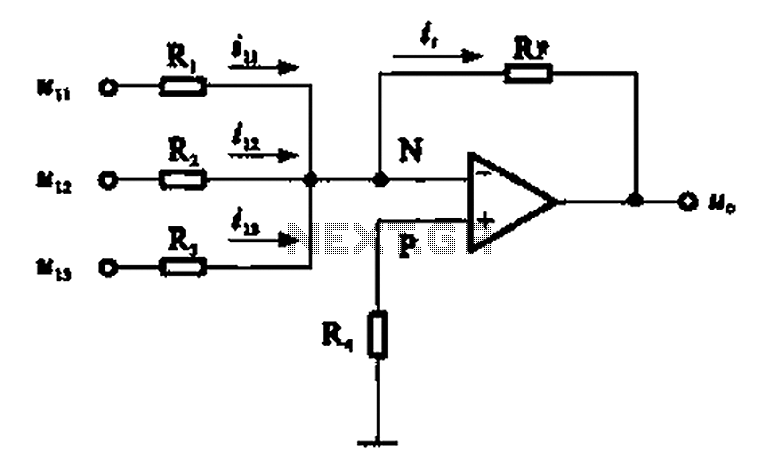
An adder circuit, specifically the inverting adder circuit, utilizes the inverting input of an operational amplifier to process signals. Voltage inputs are added through resistors connected to the inverting input terminal of the operational amplifier. The circuit configuration, as...
This amplifier was born out of a need to use two sets headphones with my computer's sound-card. The design presented here is a 50mW power amplifier meant for phones with impedances of 32 Ohms and greater. I chose this...
This type of design can produce a very high amperage current for a fraction of a second that can be used to do some useful work if properly harnessed. A point to remember is that Paul Baumann built his...
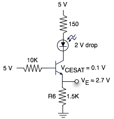
The schematic represents a relatively simple transistor circuit. Analyzing such schematics evokes memories of college days spent studying electrical engineering. However, the complexity of the schematic can be daunting after a long time away from the subject. To refresh...
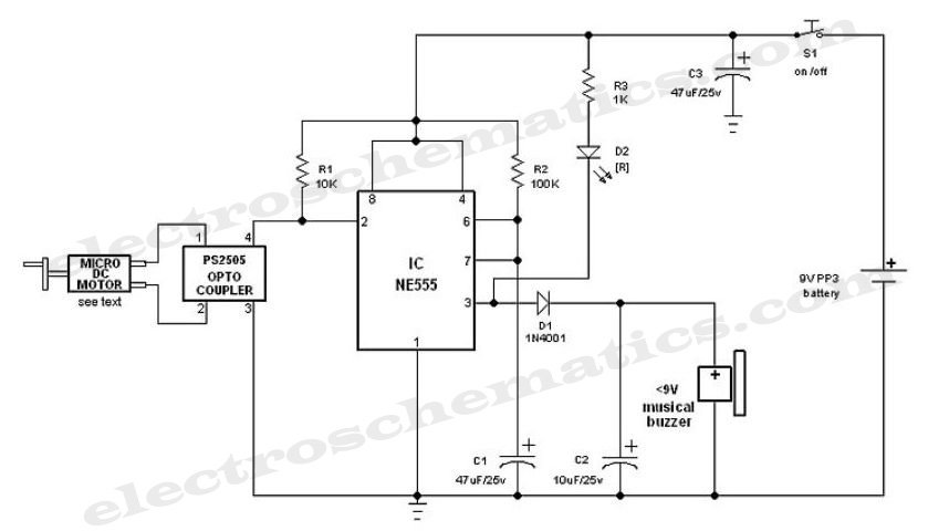
This circuit is 12 volt motors and lights well regulated. The scheme operates with PWM (Pulse Width Modulation). By IC1, a 555 is a square wave generated by a controllable duty cycle. This means that the width of the...
Warning: include(partials/cookie-banner.php): Failed to open stream: Permission denied in /var/www/html/nextgr/view-circuit.php on line 713
Warning: include(): Failed opening 'partials/cookie-banner.php' for inclusion (include_path='.:/usr/share/php') in /var/www/html/nextgr/view-circuit.php on line 713