
11W Stereo/22W Mono Power Amp Using TDA1519C

The TDA1519C power amplifier is designed for high-efficiency audio applications, making it suitable for various consumer electronics, including televisions, home audio systems, and portable devices. The device's dual-channel architecture allows for flexible configurations, enabling both stereo and mono operations, which is advantageous for different audio setups. The integrated mute/standby function is particularly useful in applications where power efficiency is critical, as it minimizes idle power consumption.
The input impedance of the amplifiers ensures compatibility with a wide range of audio sources, while the substantial voltage gain allows for significant amplification of weak audio signals. The thermal protection features are essential for maintaining the integrity of the device during prolonged operation, particularly in high-power scenarios. This ensures that the amplifier can handle demanding audio signals without risk of damage.
For practical implementation, careful attention should be given to the layout of the circuit to minimize noise and interference. Proper grounding techniques and the use of decoupling capacitors near the power supply pins will enhance performance. Additionally, selecting appropriate heatsinking solutions will ensure that the amplifier operates within safe temperature limits, thus prolonging its lifespan and reliability in various applications. Overall, the TDA1519C represents a robust solution for modern audio amplification needs.Integrated AF power amps have seen great improvements in recent years offering improved power and easier use. The TDA1519C from Philips contains two power amplifiers providing 11 W per channel stereo or 22 W mono when the two channels are connected in a bridge conguration.
The special in-line SIL9P package outline allows the chip to be convenie ntly bolted to a suitable heatsink. The TDA1519CSP is the SMD version, in this case the heat sink is mounted over, and in contact with, the top surface of the chip. The operating voltage of this device is from +6V to +17. 5V. The two channels of the amplifier are different in that one channel, between pins 1 and 4, is a non-inverting amplifier, while the other between pins 9 and 6 is an inverting amplifier.
It is therefore necessary in stereo operation, to wire the speakers so that one of them has its polarity reversed. Each amplifier has an input impedance of 60k and a voltage gain of 40dB, i. e. 100 times. When both amplifier are used in a bridge conguration, the inputs are in parallel so that the input impedance will be 30k.
A combined mute/standby function is provided on pin 8. In its simplest form this can be connected to the positive rail via a switch. When the switch is open the amplifier will be in standby mode and current consumption is less than 100 µA. When the switch is closed, the amplifier will be operational. A circuit is also shown that uses the mute input to prevent the annoying switch-on plop heard when power amps arerst switched on This is caused by the rush of current to charge capacitors C1 and C2.
The circuit shown generates a ramp voltage, which is applied to pin 8. At switch on, as the voltage rises from 3. 3 V to 6. 4 V, the amplifier will switch out of standby mode and into mute mode allowing C1 and C2 to charge. Only when the ramp voltage on pin 8 reaches 8. 5V will the amplifier switch into active mode. Protection built into the TDA1519C would seem to make it almost foolproof. The two outputs can be shorted to either of the supply rails and to each other. A thermal shutdown will prevent overloading and the power supply input is protected against accidental reversal of the supply leads up to 6V. 🔗 External reference
Related Circuits
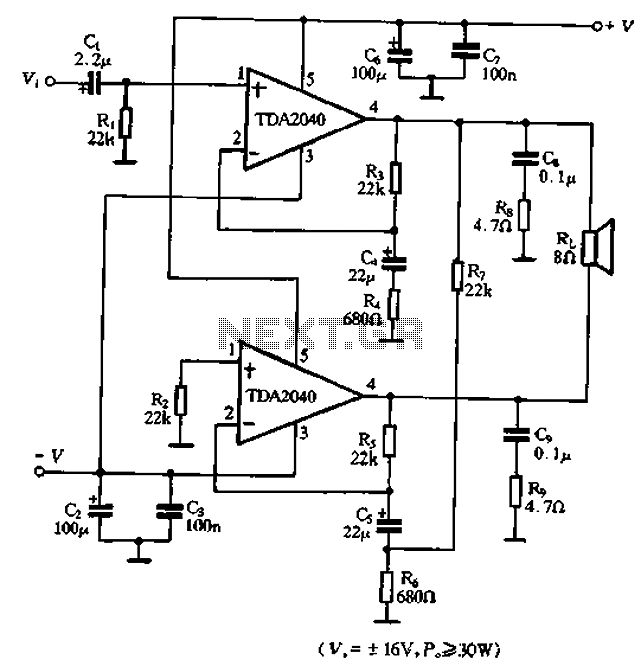
The TDA2040 is a power audio amplifier with a wider operating voltage range compared to the TDA2030, ranging from 4V to 20V. It can deliver an output power of 18W at a load of 4 ohms when supplied with...
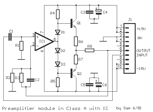
The original description discusses an application that is reputed for its high-quality sound. This superior sound quality is attributed to the operation of the entrance transistors at Class A. The sound quality is largely dependent on IC1, which needs to...
The following circuit illustrates an Automatic Light Dimmer Circuit Diagram utilizing a 1N4007 diode. Features include integration within a wall-mounted box. The Automatic Light Dimmer Circuit is designed to adjust the brightness of a light source automatically based on ambient...
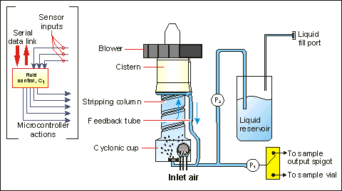
A schematic representation of the SASS 2400 is shown in Figure 2 below. The cyclone has four main sections: a cyclonic cup, stripping column, cistern, and water feedback loop. A high-efficiency, brushless centrifugal blower at the cyclone exit pulls...
After restoring a Fisher 400, the search for another tube amplifier began, motivated by a desire to apply newly acquired skills. Importing equipment from the USA to the European Union proved costly, with shipping fees around $200 to $250,...
After one has built a QRP transmitter, it would be interesting to know the exact amount of output power. Without a power meter, the peak to peak voltage Vss is measured at a 50-ohm resistance (dummy load) with the...