
Thermal Power Meter

Effective value measurement Independent of the curve shape Linear scaling of the indicator Easy calibration by a multimeter Stable control at each setpoint Dissipation-free power amplification
Part Value Fa, Fb KTY10-6 , KTY81-210 e.g. R25 C° = 2000 Ohm, 1 % Ra,Rb 50 Ohm, 4 W 2 x 100 Ohm, 2 W each, 1 % Metall or carbon type R1,2 2.7 kOhm, 1% R3 22 kOhm R4 10 kOhm R5 33 kOhm P1 100 Ohm, lin. P2 50 kOhm, lin. C1,2 4.7 nF C3 1000 uF electrolytic cap., 10 V C4 22 nF C5 1000 uF electrolytic cap., 25 V IC1 TL494CN, KA7500, IRMO2 etc. M 100 uA meter Q3 50 V NMOS power FET, BUZ21, IRFZ44 R6 1 kOhm Ra* 50 Ohm, 4 x 2 W 2x (180 Ohm parallel to 220 Ohm) Rb*
The circuit described is a power measurement system designed for QRP transmitters, utilizing both voltage measurement and thermal conversion techniques to ascertain output power. The voltage measurement method involves connecting an oscilloscope to a dummy load, typically rated at 50 ohms, to determine peak-to-peak voltage (Vss). The power output is calculated using the formula \( P = \frac{V^2}{R} \), where the effective voltage (Vrms) is derived from the peak-to-peak voltage. However, this method is subject to various errors, including resistance changes in the dummy load and inaccuracies in the oscilloscope readings.
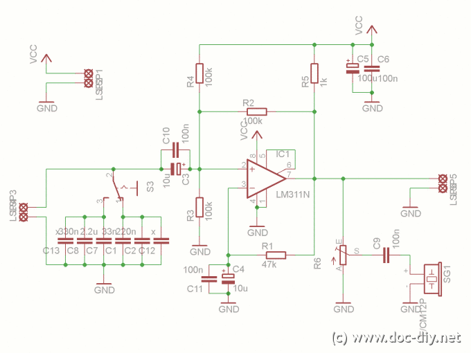
An alternative method employs thermal conversion, using a bridge circuit with temperature sensors (Fa and Fb) and resistors (Ra and Rb) to maintain equal temperatures. The power dissipated in Rb is directly proportional to the RF power dissipated in Ra. This method utilizes an operational amplifier configured as a PI controller to adjust the voltage across Rb, ensuring that the heat generated corresponds to the RF power. The design incorporates a switching regulator (TL494) to minimize losses and stabilize the output voltage, improving measurement accuracy and response time.
The components used in the circuit include precision resistors, temperature sensors, and a NMOS power FET rated for 50V, ensuring that the system can handle the required power levels without overheating. The circuit is designed for ease of calibration and stable operation across varying setpoints, with a linear scaling indicator for the measured power output. The final design aims to provide accurate power measurements while minimizing the impact of non-linearities and thermal effects.After one has built a QRP transmitter, it would be interesting to know the exact amount of output power. Without a power meter the peak to peak voltage Vss is measured at an 50 ohm resistance (dummy load) with the available oscilloscope.
Now the power rate can be calculated according to the formula P = V x V / R. For V the effective voltage rate Vrms = 0,707 x Vss / 2 is to be used. With this type of power determination by a voltage measurement there are different sources of error: A dummy load resistance deviating from 50 Ohms when heating up, the basic accuracy of the oscilloscope, the amplitude drop of the Y amplifier at high frequencies and a possibly not correctly calibrated 10:1 probe. Each more or less measured volt has an appropriate influence on the result of the calculation (power) due to V x V.
50 % deviation upward or down from the real power level is quite possible under worst case conditions. Another method of the power determination gets along without measurement of the HF voltage. It operates according to the principle of the thermal conversion. A controller ensures that the temperature at the two heating resistors Ra and Rb is identical. Rb is warmed up as long as the bridge circuit consisting of the temperature sensors Fa/b and the resistors R1/2 is ballanced. The DC power dissipated by Rb corresponds then exactly the HF power dissipated by Ra. As controller an operational amplifier with a linear amplifier (power transistor) is usually used. Rb receives thereby as correcting variable a variable voltage. Since the amount of heat is however proportional to the square of this voltage, one gets a controller loop gain proportional to V x V.
The result is a nonlinear step response and thus all well-known problems concerning the controller stability at setpoint changes. The additional power dissipation at the linear amplifier of max. 0.5 x Pmax is here only mentioned by the way. A duty cycle of tp = 0,95 x T is feasible with the parallel arrangement of the switching transistors.
The missing 5% are of principle due to the push-pull design of the switching regulator. Who needs a 5 W power meter should take into consideration that Ra/Rb have sufficient high power dissipation rating and the transistors in the regulator IC are not overloaded. If the 13.8 V supply voltage should be kept, it is recommended to reduce the Rb resistance value down to 25 Ohms at the same form factor as Ra*.
The current flow through Rb* is then approx. 0,5 A. Any 50 V NMOS power FET (Q3) can conduct this current. The modules are built in such a way, that the sensors see only half the power (max. 2,5 W). The module temperature should not exceed 100 °C. The maximum rating for the temperature sensors is specified at 150 °C. The operational amplifier in the TL494, configured as PI controller, provides for an optimal regulation quality and transient behavior at setpoint changes. The display of the measured power is very simple; a milliammeter integrates the impulses. The scaling is linear due to the removal of the square component (P ~ tp ~ Ys). The disadvantages mentioned before do not apply to the following circuit. The special of the circuit is the use of a switching regulator in place of a continuous controller. The switching regulator TL494 converts the error signal Xd into a proportional pulse duration tp. The output voltage is now constant and it is omitted thereby the disturbing square component in the control loop.
The amount of heat is adjusted exclusively over the pulse duration proportionally rising with Ys = f (Xd). The switching losses in the two switching transistors in IC1 are negligibly small. Effective value measurement Independent of the curve shape Linear scaling of the indicator Easy calibration by a multimeter Stable control at each setpoint Dissipation free power amplification Part Value Fa, Fb KTY10-6 , KTY81-210 e.g.
R25 C° = 2000 Ohm, 1 % Ra,Rb 50 Ohm, 4 W 2 x 100 Ohm, 2 W each, 1 % Metall or carbon type R1,2 2,7 kOhm, 1% R3 22 kOhm R4 10 kOhm R5 33 kOhm P1 100 Ohm, lin. P2 50 kOhm, lin. C1,2 4,7 nF C3 1000 uF electrolytic cap., 10 V C4 22 nF C5 1000 uF electrolytic cap., 25 V IC1 TL494CN, KA7500, IRMO2 etc.
M 100 uA meter Q3 50 V NMOS power FET, BUZ21, IRFZ44 R6 1 kOhm Ra* 50 Ohm, 4 x 2 W 2x (180 Ohm parallel to 220 Ohm) Rb* 🔗 External reference
Related Circuits

A simple LED voltmeter is designed to monitor the charge level in a lead-acid battery or tubular battery. The terminal voltage of the battery is displayed using four LED indicators. The nominal terminal voltage for a lead-acid battery is...
This article explains the process of constructing a basic inductance meter. The printed circuit board (PCB) layout is provided. The construction of a simple inductance meter involves several key components and a well-designed PCB layout to ensure accurate measurements of...
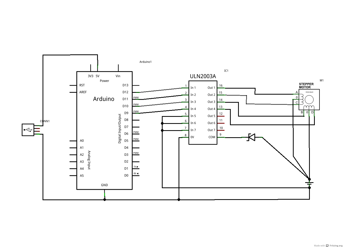
The ULN2003A and Zener diode are components from the driver board within the same device. The motor in question has five wires, while the schematic depicts a six-wire motor. It is assumed that the difference lies in the fact...
This is basically the frequency meter section of the frequency meter/pulse generator based on the AT90S2313 described elsewhere on this site, combined with the 100 MHz RF interface described in the page about the RS-232 to 100 MHz RF...
This circuit utilizes a single active component, the 4069 IC, to convert sine waves into square waves without requiring an external power source. It is designed for testing audio instruments. The circuit leverages the characteristics of the 4069 IC, which...
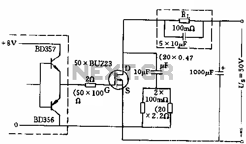
The circuit employs 50 BUZ23 field effect transistors (FETs) arranged in parallel, with a tube blocking voltage of 100V. The control power required is minimal, eliminating the risks associated with second breakdown and the positive temperature coefficient phenomenon in...