
12-24V Impulse control dimmer

Parts:
- R1 = 330Ω 2W
- R2, R3 = 2.7kΩ
- R4 = 470Ω
- R5, R6, R7 = 1.5kΩ
- P = 2 x 100kΩ
- C1 = 47µF/10V
- C2 = 10µF/10V
- C3, C4 = 0.22µF/24V Tantalum
- D1, D2 = 1N4148
- D3 = Zener 10V 1W
- T1, T2 = BC237C
- T3 = BD331
The circuit operates by modulating the power supplied to the load, allowing for precise control over the output. The use of a transistor (T3) as the primary switching element enables efficient control of high currents while maintaining low power loss. The impulse control mechanism ensures that the load receives power in short bursts, which minimizes heat generation and improves efficiency.
The resistors (R1, R2, R3, R4, R5, R6, R7) serve various functions, including setting biasing levels for the transistors and controlling the current flow throughout the circuit. The potentiometer (P) allows for adjustable control of the output, enabling fine-tuning of the load's performance.
Capacitors (C1, C2, C3, C4) are included for filtering and stability, ensuring that the circuit operates smoothly without oscillations or spikes in voltage. The Zener diode (D3) provides voltage regulation, protecting the circuit from voltage surges that could damage sensitive components.
Diodes (D1, D2) are used for signal rectification and protection, ensuring that the transistors are not exposed to reverse voltage that could lead to failure. The transistors (T1, T2) are used for signal amplification and switching, while T3 handles the main power switching, requiring careful thermal management to prevent overheating.
Overall, this circuit design is robust and efficient for controlling various types of loads, provided that adequate thermal management is implemented for the transistor T3. Proper assembly and insulation of components are critical for reliable operation.This circuit is intended for use with motors, lamps,heatings etc. Continuously from nearly zero up to maximum capacity (5-95%). Almost lossfree control by means of this impulse control. Nearly total turning moment of motors. The transistior T3 must absolutely be fastened on a heatsink with minimum dimentions of approximate 100x100x5mm. The heatsink has to be fixed insulated as the transistor has a conductive connection between the C-connection and the metal rear side.
The transistor T3 can be destroyed by short circuit or by overheating if the circuit is operated without heatsink. --------------- Parts: R1=330-2W R2,R3=2,7K R6,R7,R5=1,5K R4=470 P=2X100K C1=47UF/10V C2=10UF/10V C3,C4=0.22UF/24v TANTAL.
D1,D2=1N4148 D3=ZENER 10V-1W T1,T2=BC237C T3= BD331
Related Circuits
Connected to a burglar alarm or fire alarm, this device facilitates phone calls that play voice messages. It is controlled via DTMF actuators, allowing for immediate operation. In recent years, several telecontrols based on the SIM900 GSM module have...
A voltage-controlled oscillator (VCO) is an oscillator whose frequency is regulated by a voltage signal. The VCO discussed here can generate both triangular and square wave outputs. The control voltage can be adjusted between 5 mV and 5 V,...
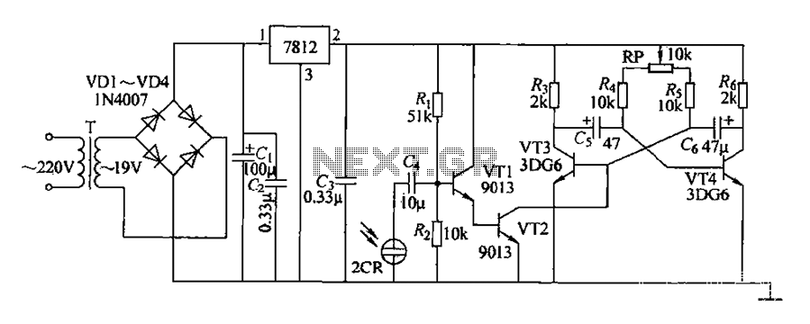
220V AC voltage is transformed by transformer T to 19V. After passing through a full-wave bridge rectifier and filter capacitor C, the voltage is regulated to DC using a 7812 voltage regulator. When the battery indicator light is illuminated,...
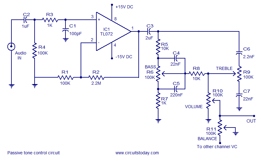
Tone control circuit utilizing an operational amplifier and a Baxandall passive tone control configuration. The overall gain is 25 dB, with a boost and cut capability of 20 dB. The circuit is powered by a dual 15V supply. The tone...
Two stepper motors are to be controlled by a dsPIC microcontroller. The programming of the microcontroller has been completed, but there is confusion regarding the use of the L298 driver. Assistance is needed with the circuit design. To control two...
I found this circuit in my files. I don't know where it came from, but it looks like I photocopied it from somewhere years ago. I have been told that it came from "The Robot Builder's Bonanza", by Gordan...