
10 Hz to 10 Khz Voltage Controlled Oscillator

The voltage-controlled oscillator (VCO) is a critical component in various electronic systems, serving as a signal generator with variable frequency outputs that are dependent on the control voltage applied at its input. In the described VCO circuit, the design allows for the generation of both triangular and square waveforms, providing versatility for different applications.
The operational range of the control voltage, spanning from 5 mV to 5 V, enables the user to modulate the output frequency from 10 Hz to 10 kHz. This range is particularly useful in applications such as signal modulation, tone generation, and frequency synthesis, where precise frequency control is necessary.
The schematic diagram illustrates a micropower VCO circuit that is designed to operate efficiently with minimal power consumption. With a current draw of only 50 µA from a single 5 V supply, this circuit is suitable for battery-operated devices and low-power applications. The use of a quad CMOS configuration allows for the integration of multiple functions within a single package, reducing component count and overall circuit complexity.
The triangular wave output can be utilized for applications requiring linear ramp signals, while the square wave output is ideal for digital signal processing and timing applications. The ability to produce both waveforms from a single VCO circuit enhances its utility in various electronic designs.
To implement this VCO circuit, careful consideration should be given to the selection of components, including the operational amplifiers and resistors used in the ramp generator configuration. The performance of the VCO can also be influenced by external factors such as temperature and power supply stability, which should be accounted for in the design process to ensure reliable operation across the specified frequency range.Voltage-controlled oscillator (VCO) is an oscillator that its frequency is controlled using a voltage signal. The VCO described here provide both triangular and square wave output. The control voltage can be varied between 5 mV to 5 V, to produce oscillation frequency from 10 Hz to 10 KHz.
Here is the schematic diagram of the circuit: This is a sc hematic diagram of a micropower voltage-controlled oscillator circuit. This circuit can generate square and triangle wave outputs and only need 50 µA from a single 5 V supply. This circuit consist of combination of an inexpensive quad CMOS Continue reading †’. VCO (voltage controlled oscillator) is an electronic signal generator which produce a signal that has variable frequency depends on a voltage level at its control input.
Many VCO circuits are based on ramp generator to produce a variable frequency output, Continue reading †’. 🔗 External reference
Related Circuits
Examine a traditional Hartley oscillator circuit, and you'll note its trademark: a tapped inductor that determines the frequency of oscillation and provides oscillation-sustaining feedback. Although you can easily calculate the total inductance required for a given frequency, finding the...
The frequency formula of a 555 oscillator is well-known. For given resistors and capacitors, the frequency can be calculated using a specific formula derived from mathematical principles. The 555 timer IC is widely used in various applications, including oscillators, timers,...
This is a sine wave oscillator circuit, also known as an amplitude-stabilized sine-wave oscillator. It can provide a high purity sine wave output. The sine wave oscillator circuit is designed to generate a stable and high-quality sine wave output, which...
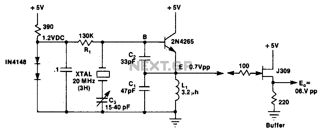
L1 and C1 are selected to resonate at a frequency below the desired crystal harmonic but above the crystal's next lower odd harmonic. Capacitor C2 should have a value between 30-70 pF, independent of the oscillation frequency. There is...
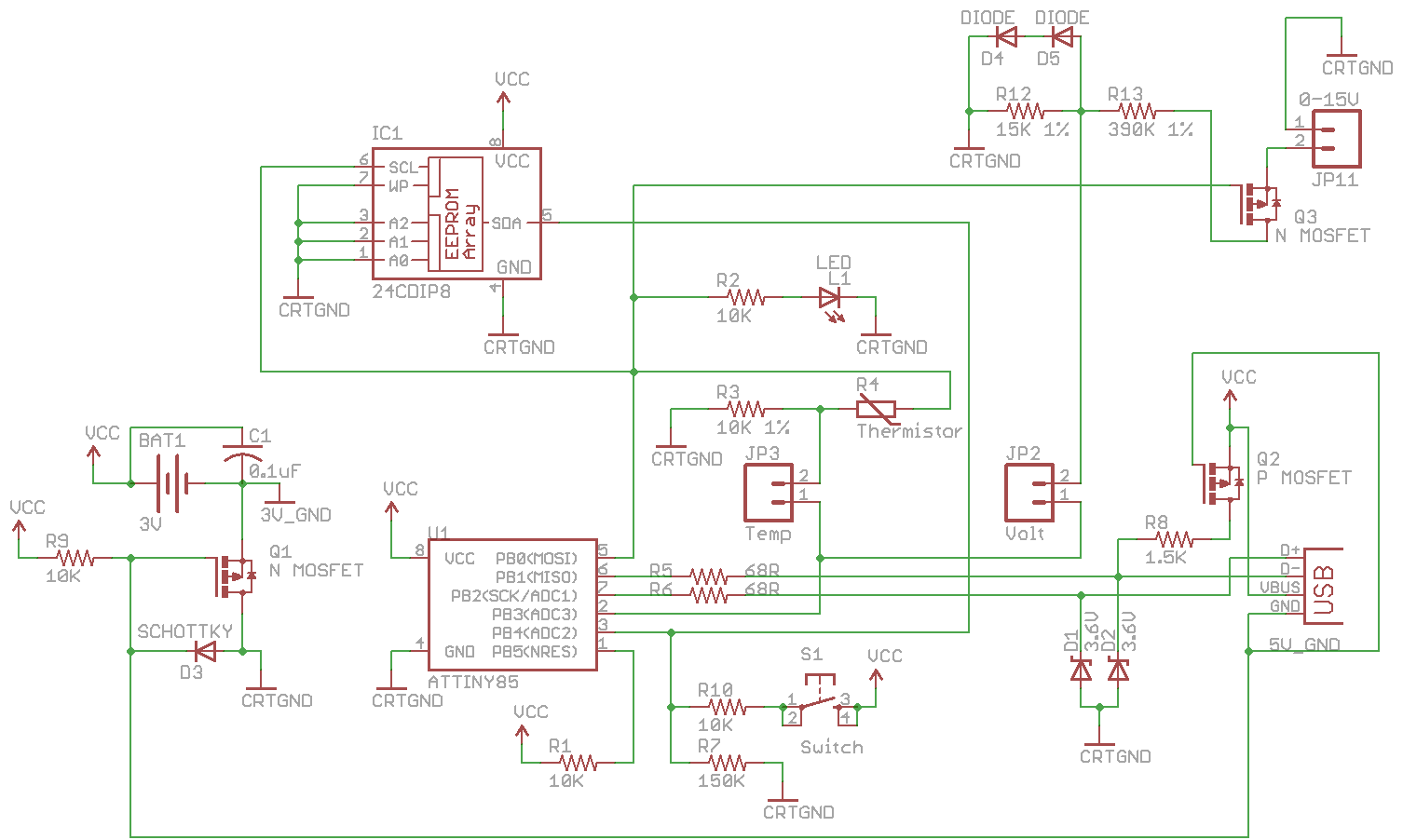
Combine the SATL and SAVL together. The schematic was updated with the voltage sensing circuit. A MOSFET was added to draw power from the voltage source only when needed. There are two jumpers, Temp and Volt, allowing the user...
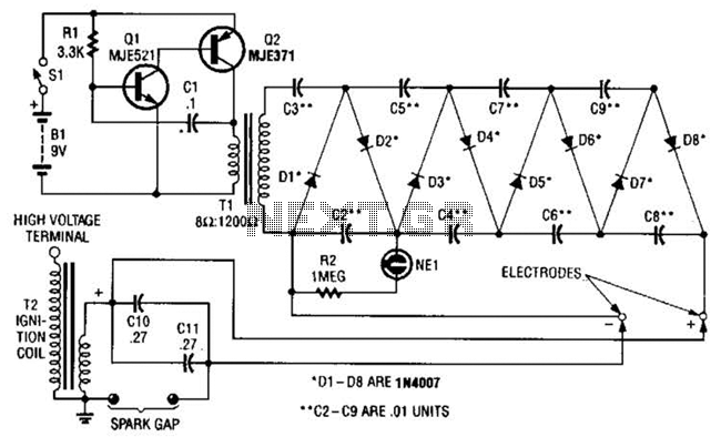
This circuit employs a transistor oscillator and a voltage multiplier to charge capacitors CIO and CI1 to a high voltage. When the spark gap breaks down, T2 generates a high-voltage pulse through the discharge of capacitors CIO and CI1...