
12 Volt Car Lamp Dimmer Circuit Design using 555 Timer

The 12 Volt Car Lamp Dimmer Circuit utilizes a 555 Timer in astable mode to control the brightness of a 25-watt car lamp. The circuit consists of a 555 Timer IC, resistors, capacitors, and a transistor to handle the load.
In this configuration, the 555 Timer generates a PWM (Pulse Width Modulation) signal, which is used to control the average power delivered to the lamp. The duty cycle of the PWM signal can be adjusted by varying the resistance values of the connected resistors, allowing for precise control over the brightness of the lamp.
Typically, a potentiometer is included in the circuit to enable the user to adjust the resistance, thereby altering the duty cycle and achieving the desired dimming effect. The output from the 555 Timer drives a transistor, which acts as a switch to control the lamp. The transistor must be chosen based on the current requirements of the lamp to ensure it can handle the load without overheating.
Capacitors are used in the timing circuit to stabilize the operation of the 555 Timer and filter any noise that may affect performance. The circuit operates at 12 volts, making it suitable for automotive applications.
Overall, this dimmer circuit is a practical solution for controlling the brightness of car lamps, enhancing both functionality and aesthetics while providing an efficient use of power.The following schematic diagram shows the 12 Volt Car Lamp Dimmer Circuit Design using 555 Timer. This circuit design can be used to dim a standard 25 watt.. 🔗 External reference
Related Circuits
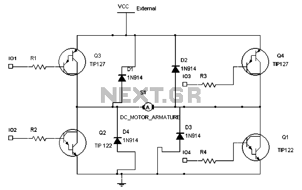
To maintain a constant speed of the motor under varying load conditions, a control application circuit is required. An H-Bridge circuit can be utilized to manage both the speed and direction of the motor. The accompanying diagram illustrates the...
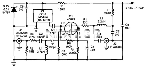
This converter utilizes a 40673 MOSFET to heterodyne the 5.5 to 8 MHz TVRO subcarriers to the FM broadcast band, enabling the use of a stereo receiver for high-fidelity stereo reception of TV sound subcarriers. Z1 is a prepackaged...
This simple CPO is for those who want to practice Morse Code in a different way, ie without the morse key. It can be also used as a touch operated door bell. The popular timer IC555 is wired as...
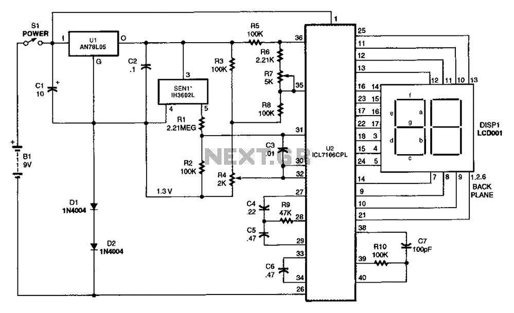
The output DC voltage of sensor SEN1 changes linearly in response to variations in relative humidity. This DC voltage is routed through resistors R1 and R2 to the analog-to-digital (A/D) converter chip U2. Resistor R4 is connected to ground,...
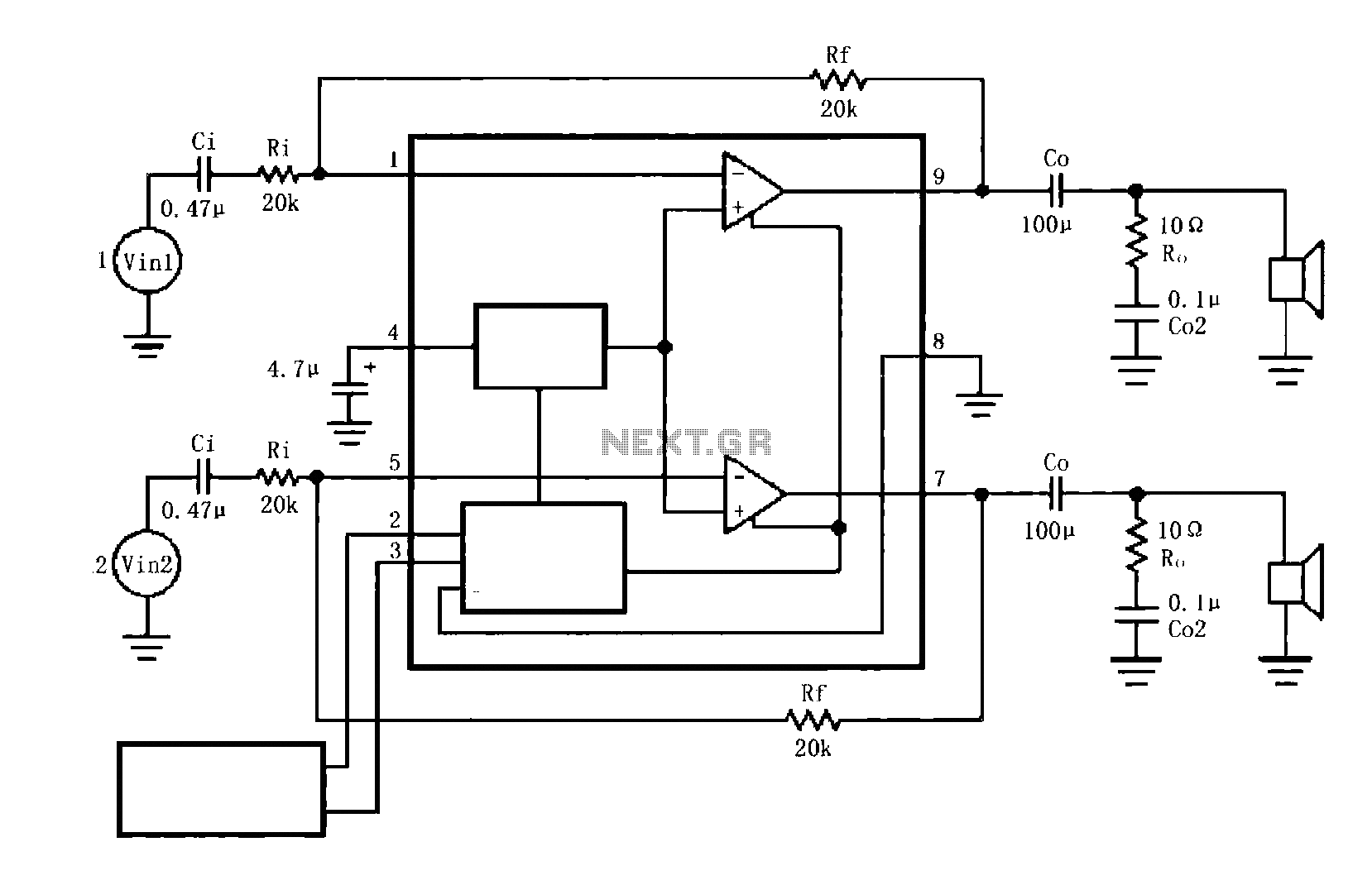
The circuit illustrated is a typical configuration for the LM4916 two-channel amplifier. The left and right channel audio signals are fed into the LM4916, which amplifies them internally. The output is then delivered through a coupling capacitor (Co) to...
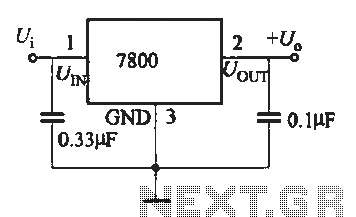
A fixed three-terminal integrated voltage regulator can be directly employed in various electronic devices as a voltage regulator. It features internal protections such as overcurrent protection, thermal protection, and safe operating area protection, making the circuit easy to use,...