
The H-Bridge Circuit Control Design in DC Motor Application
The H-Bridge circuit is a crucial component in motor control applications, particularly for DC motors. It consists of four switches (transistors or MOSFETs) arranged in a bridge configuration. By controlling the state of these switches, the circuit can reverse the polarity of the voltage applied to the motor, thus changing its direction of rotation.
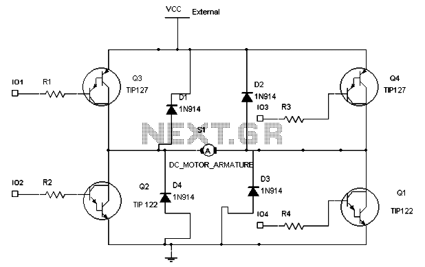
In a typical H-Bridge setup, two pairs of switches are used: one pair for forward operation and the other for reverse. When the switches in one diagonal (e.g., Q1 and Q4) are closed, current flows through the motor in one direction, causing it to rotate forward. Conversely, when the opposite diagonal switches (Q2 and Q3) are activated, the current direction is reversed, and the motor rotates in the opposite direction.
The control application must also incorporate pulse-width modulation (PWM) techniques to regulate the speed of the motor. By varying the duty cycle of the PWM signal fed into the control inputs of the H-Bridge, the effective voltage applied to the motor can be adjusted. This allows for smooth acceleration and deceleration, as well as efficient energy usage.
Additionally, it is essential to include protective features in the circuit design, such as current sensing and thermal protection, to prevent damage to the motor and the H-Bridge components. Feedback mechanisms can be integrated to monitor the motor's speed and load conditions, allowing for real-time adjustments to maintain the desired performance.
Overall, the H-Bridge circuit serves as an effective solution for controlling the speed and direction of a DC motor, making it suitable for various applications in robotics, automation, and other fields requiring precise motor control.In order to keep the speed of the motor constant when loads are applied, a control application circuit is needed to apply the purpose. The H-Bridge circuit may control the speed and direction of the motor. The below diagram shows H-Bridge with 4 inputs and external power supply, the control application must allow the motor to be operated in forward and reverse directions.
The motor will rotate. 🔗 External reference
Related Circuits
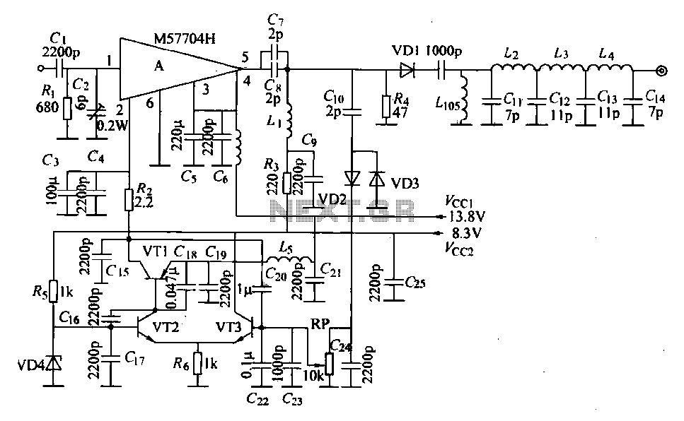
The FM radio transmitter is a high-frequency amplifier circuit that utilizes the Mitsubishi frequency set, specifically the M57704H discharge path. It operates within the frequency range of 457-458 MHz and has a transmission power of 5 watts. As illustrated...
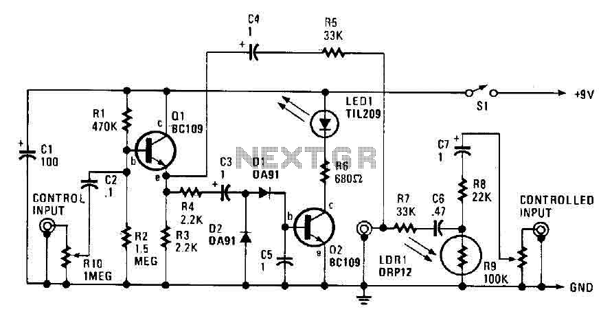
The automatic fader reduces the background music level when narration is in progress. The control input through RIO, a preset audio level control, is directed into an emitter-follower buffer stage (Q1). This buffer provides high input impedance and ensures...
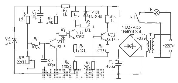
The circuit operates as a light-activated switch that controls white moving lights. It features high sensitivity, stable performance, and good anti-interference characteristics. A photosensitive resistor (RI) is employed to detect ambient light levels. During the day, the resistor exhibits...
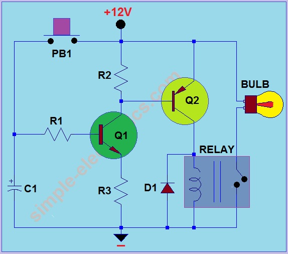
This circuit operates by activating a headlight when the push-button PB1 is pressed. The headlight remains illuminated for a predetermined duration, which can range from several seconds to minutes, before automatically turning off. When PB1 is engaged, capacitor C1...
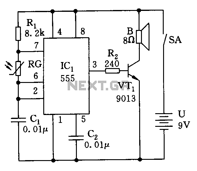
The electronic circuit simulates bird sounds under varying lighting conditions, particularly influenced by neon light irradiation, resulting in fluctuating and changing tones. The sound produced is continuously variable. The schematic of this circuit is provided. The described electronic circuit utilizes...
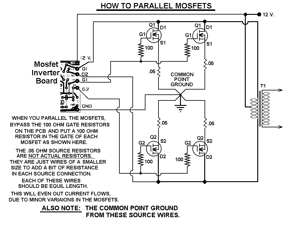
This 1000-watt power inverter circuit diagram is based on the MOSFET RF50N06. For increased power output, additional MOSFETs can be paralleled with the RF50N06. These MOSFETs are rated for 60 volts and 50 amps. It is essential to connect...