
120 vac lamp dimmer

The full wave phase control circuit operates by utilizing the principles of phase control to regulate the power delivered to a resistive load. The configuration comprises four diodes arranged in a bridge rectifier setup, which allows for the conversion of the alternating current (AC) input into a direct current (DC) output that feeds into the anode of the SCR. The SCR acts as a controlled switch, allowing current to flow through the load only when triggered appropriately.
The two small-signal transistors function as a timing mechanism, responding to the voltage across the 2.2 µF capacitor. As the AC waveform progresses, the capacitor charges until it reaches the threshold voltage of approximately 8 volts. At this point, the transistors switch on, effectively discharging the capacitor through the gate of the SCR. This discharge triggers the SCR, enabling it to conduct current and power the load.
The 50 kΩ resistor plays a crucial role in determining the timing of the SCR's conduction. By adjusting this resistor, the user can control the rate at which the capacitor charges, thereby influencing when the SCR will be triggered within each AC cycle. A lower resistance allows for quicker charging, resulting in earlier SCR activation and increased average voltage across the load. Conversely, a higher resistance delays the triggering, reducing the average voltage delivered to the load.
The 15 kΩ resistor serves as a calibration tool, allowing for fine-tuning of the output voltage. This adjustment is essential to account for variations in component tolerances, ensuring that the system operates effectively across different conditions. The careful selection and adjustment of these resistors are vital for achieving the desired performance of the circuit.
Safety precautions must be observed when working with this circuit, particularly due to its connection to the AC line, which poses a risk of electric shock. Proper insulation and handling practices should be employed to mitigate these risks during operation and maintenance.The full wave phase control circuit below was found in a RCA power circuits book from 1969. The load is placed in series with the AC line and the four diodes provide a full wave rectified voltage to the anode of a SCR. Two small signal transistors are connected in a switch configuration so that when the voltage on the 2.
2uF capacitor reaches about 8 volts, the transistors will switch on and discharge the capacitor through the SCR gate causing it to begin conducting. The time delay from the beginning of each half cycle to the point where the SCR switches on is controlled by the 50K resistor which adjusts the time required for the 2uF capacitor to charge to 8 volts.
As the resistance is reduced, the time is reduced and the SCR will conduct earlier during each half cycle which applies a greater average voltage across the load. With the resistance set to minimum the SCR will trigger when the voltage rises to about 40 volts or 15 degrees into the cycle.
To compensate for component tollerances, the 15K resistor can be adjusted slightly so that the output voltage is near zero when the 50K pot is set to maximum. Increasing the 15K resistor will reduce the setting of the 50K pot for minimum output and visa versa.
Be careful not to touch the circuit while it is connected to the AC line. 🔗 External reference
Related Circuits

Introduction The ignition timing lights commonly used range from simple neon to complex units. Neon timing lights have a drawback due to their low light output, necessitating operation in subdued lighting. This presents a safety hazard, as users tend...
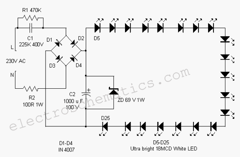
This white LED light illuminates the porch with cool white light. The circuit features a simple and energy-saving design. Its current consumption is practical. The white LED light circuit is designed to provide efficient illumination while minimizing energy usage. The...
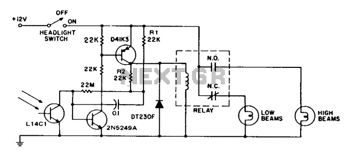
This circuit switches car headlights to the low beam state when it detects the lights of an oncoming vehicle. The received light is of low intensity and highly directional, indicating the use of a lens with the detector. A...
There are several situations where a power failure can be particularly challenging to manage, especially in the bathroom. This compact circuit is designed to be cost-effective, particularly beneficial during a shower. The backup lamp remains off as long as...
This circuit gradually illuminates a 120VAC lamp over an approximate 20-minute period. A bridge rectifier provides 120V DC to the MOSFET and the 60-watt lamp. A 6.2K, 5-watt resistor along with a Zener diode is utilized to reduce the...
Very simple, versatile modular design. The purpose of this circuit was to create a ring in which LEDs or Lamps illuminate sequentially. Its main feature is a high versatility: you can build a loop containing any number of LEDs...